





Faze4 Robotic Arm
 B
Bこのプログラムについて
Faze4 — 6-Axis Cycloidal Robot Arm
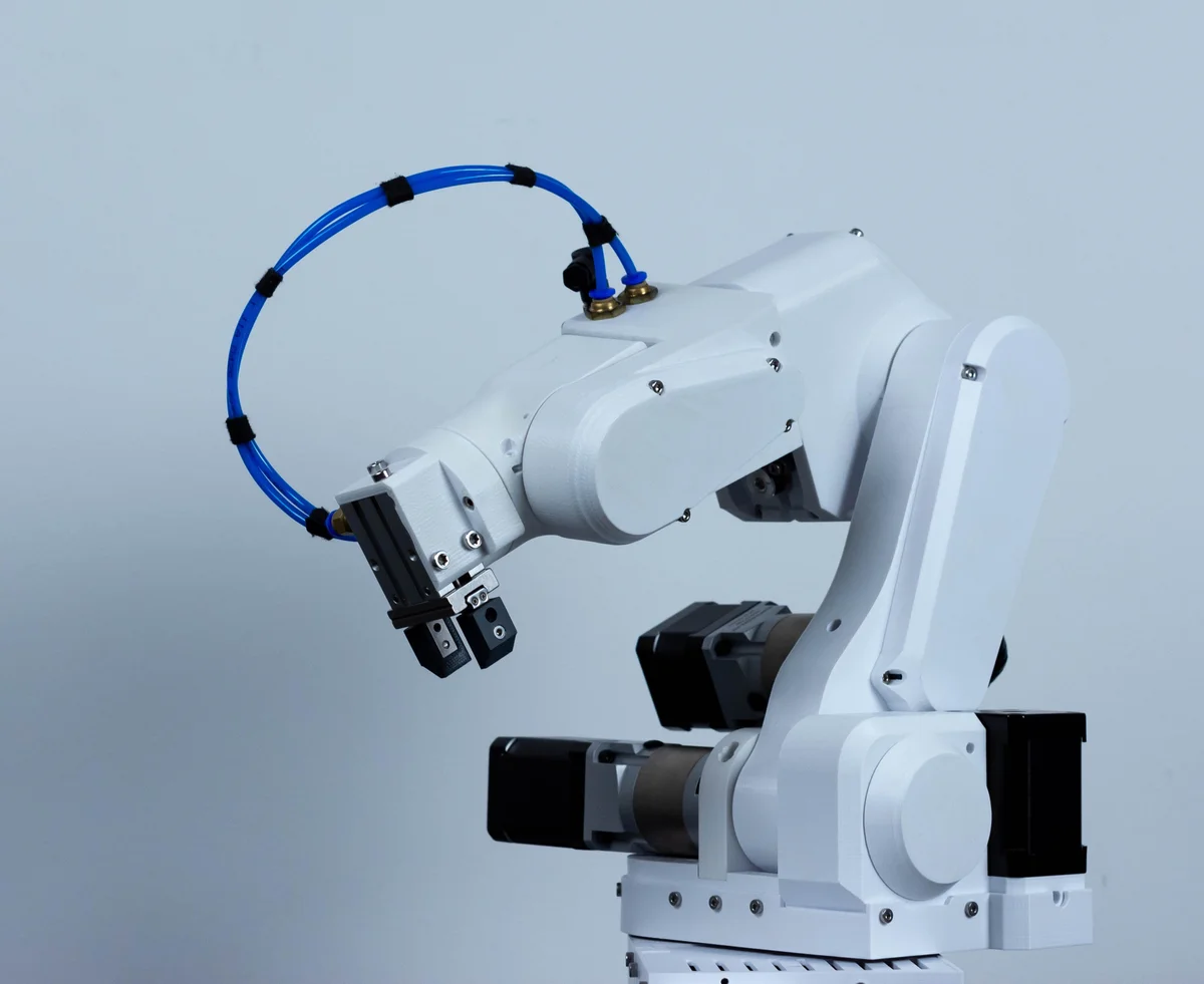
Faze4 is a full-size 6-DOF desktop industrial-style robot arm, designed by Petar Crnjak and released by Source Robotics. It uses cycloidal reducers on all major joints (instead of the usual harmonic drives or belts), which gives it high payload capacity, near-zero backlash, and a noticeably beefier feel than a typical hobby arm.
What it is
- 6 rotational joints (classic industrial arm kinematics)
- Cycloidal reducers on joints 1–4
- NEMA 23 and NEMA 17 steppers with closed-loop encoder feedback
- Custom distribution PCB that fans out from a single controller to all joint drivers
- ~1000 parts total, roughly 15 kg assembled
- Work envelope ~650 mm reach
What it does
Faze4 lives in the "aspirational build" slot on this catalog. It's not a weekend project — it's a multi-week build with real machining decisions, bearings to press, and PCBs to populate. What you get at the end is a genuinely industrial-feeling arm that can move real weight and repeat positions accurately enough to pick and place non-trivial payloads.
Typical uses the community has shown:
- Pick-and-place with suction or a custom end-effector
- Light pen plotting and laser marking
- Educational kinematics demos (forward/inverse, Jacobians, singularities all matter here in a way they don't on a 5g gripper toy)
- ROS/MoveIt integration experiments
Cost and effort
Roughly $1000 in parts (steppers, bearings, PCBs, fasteners, some aluminum) plus ~3 kg of filament for the printed structure. Expect 40–80 hours of build time end-to-end.
Printing
The full Faze4 printable set is large (~1000 parts, ~3 kg of filament) and is distributed upstream as a single archive, STL_V2.zip, in the Faze4-Robotic-arm repo — not as individual files. Download and unpack that ZIP for the complete, canonical print set.
The files attached here are a curated subset of the real printable detail parts pulled from STL_V2.zip — joint covers, lids, pulleys, the e-stop housing, and the gripper/end-effector mounts:
- Base & joint 1:
J1_bottom_lid,main_base_blocker,fan_cover - Electronics:
Electronics_case_v1_1,lid_electronics - Elbow (joint 3):
Elbow_part,Elbow_lid_1,Elbow_lid_2 - Joints 4/5 drivetrain:
J4_bearing_backplate,J4_limiter,J4_output_pulley,HTD3_48_J5_pulley,J5_part,J5_electronics_lid - E-stop module:
ESTOP_TOP,ESTOP_BOTTOM - End-effector (pick one gripper style):
Gripper_ARMS(mechanical jaws),Pneumatic_gripper_holder(suction/air),vacuum_gripper_holder(vacuum) — these three are mutually-exclusive end-effector options; choose the one matching your tooling.
Removed from the Print-All set: the seven URDF visualization/collision meshes (base_link, rotary_base, nadlaktica, lakat, podlaktica, saka, hvataljka). Those are byte-identical to the loose URDF_FAZE4/meshes/ files in the repo — single solid blobs representing whole links for simulation/RViz. They are not printable assemblies (each real link is many separate parts), so printing them would yield un-assemblable monolithic chunks. They have been dropped to keep Print-All meaningful.
This is an aspirational, multi-week build: the attached parts do not constitute the complete arm. Use STL_V2.zip upstream for the authoritative full set, and the assembly PDF + Read the Docs for build order and quantities.
Software
Firmware ships in the upstream Faze4_test_code_1.0 tree (teensy/Arduino-style C++). The community has working ports to ROS via a separate package. The control surface exposed by this orobot program assumes a Raspberry Pi front-end talking to the arm's low-level controller over serial — see Documentation for the bridge contract.
Attribution & license
- Designer: Petar Crnjak / Source Robotics
- Upstream: https://github.com/PCrnjak/PAROL6-Desktop-robot-arm (sibling project — see Faze4 repo for this specific arm)
- Hardware license: CERN OHL S (Strongly Reciprocal)
- Build docs: https://source-robotics.readthedocs.io/
- Community: Source Robotics Discord + Hackaday build log
Links
- Upstream repo: https://github.com/PCrnjak/Faze4-Robotic-arm
- Read the Docs: https://source-robotics.readthedocs.io/
- Hackaday writeup: https://hackaday.com/tag/faze4/
🖨 印刷ファイル (19)
Electronics_case_v1_1.STL
J1_bottom_lid.STL
fan_cover.STL
lid_electronics.STL
main_base_blocker.STL
Elbow_lid_1.STL
Elbow_lid_2.STL
Elbow_part.STL
J4_bearing_backplate.STL
J4_limiter.STL
ESTOP_BOTTOM.STL
ESTOP_TOP.STL
必要なハードウェア
| Part | Notes |
|---|---|
| Stepper motors | 6 joints; specific models in official BOM |
| Motor drivers | One per stepper |
| 3D printed arm links | All structural parts printable in PLA/PETG |
| Bearings | Multiple sizes per joint; sizes in BOM |
| Lead screws + nuts | For linear joints |
| M3/M4/M5 hardware | Bolts, nuts, heat inserts throughout |
| Arduino Mega 2560 | Main control board |
| CNC shield + stepper drivers | Motion control |
| 24V power supply | Powers motors |
似たロボットを探す