3D Print Open Source AI Robots
 Mobile Robots
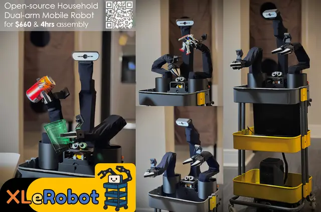
XLeRobot Dual-Arm Mobile Home Robot
$660Low-cost dual-arm mobile robot for embodied AI and household manipulation
 Humanoids
Reachy Mini
$399Expressive open-source robot for hackers and AI builders
 Mobile Robots
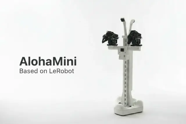
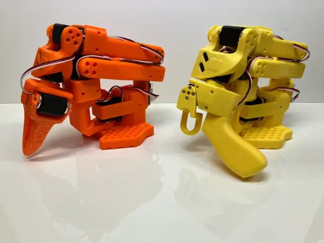
AlohaMini Dual-Arm Mobile
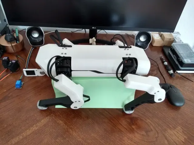
$750AlohaMini — Dual-Arm Mobile Manipulation Platform A miniaturized Aloha-style dual-arm mobile platform with a motorized vertical lift column. Two SO-ARM101 follower arms sit on a shared lift tower mounted to a three-wheel omni base, giving the platform a tabletop-to-floor reach envelope that makes real household-scale manipulation possible at hobbyist cost. What makes AlohaMini distinctive Most DIY bi-manual mobile bases have one big gap: they're too short. An SO-ARM on a fixed 20-cm pedestal can't pick up something on the floor or reach a countertop — the workspace is stuck at one height. AlohaMini solves this with a powered vertical lift that raises both arms together, scanning the full vertical reach of a human workspace. Paired with: Two SO-ARM101 follower arms (leader arms for teleop are also included in the STL set) A three-omniwheel kiwi drive base (bearing-mounted axles, printed chassis) Seeed Studio XIAO + WaveShare Dynamixel bus driver mounts Camera wrist mounts on both arms What you can do with it Imitation learning at floor and table height — record bimanual episodes where the arms need to descend to grab something off the floor, then lift to place it on a surface. Mobile bimanual teleop — pair with two leader arms (also in the STL set) to drive both follower arms plus the base from a single operator. VLA training data collection — the shared base frame + lift + dual arms is close to the canonical "robot" embodiment used in recent VLA papers (RT-2, OpenVLA). Household tasks — clearing a dining table, loading a dishwasher, or picking laundry off the floor — all things a fixed-height arm can't attempt. Printed parts ~60 STLs — dual SO-ARM101 arms (follower grippers + leader handles), motorized lift column, 3-omniwheel base, battery tray, VR teleop handles; see Print Files. Attribution & license Designer: Yi-Teng Li (liyiteng) Upstream: https://github.com/liyiteng/AlohaMini License: Apache 2.0 Built on: SO-ARM101, LeKiwi base geometry, and the ALOHA/ALOHA2 dual-arm research lineage from Stanford Links Upstream: https://github.com/liyiteng/AlohaMini LeRobot: https://github.com/huggingface/lerobot ALOHA paper: https://tonyzhaozh.github.io/aloha/ Build Guide Hardware assembly guide (BOM, wiring, mechanical assembly): github.com/liyiteng/AlohaMini/blob/main/docs/hardwareassembly.md Printing This is one complete dual-arm mobile platform: two SO-ARM101 follower arms + two leader arms (for teleop) on a shared lift column over a 3-omniwheel base. The 20 STLs use a role-prefix naming scheme, and most are printed in multiples — printing one of each gives only a fraction of a build. Quantities below are per platform: — shared SO-ARM101 arm parts (print 4× each: 2 followers + 2 leaders): DBaseSO101Lekiwi, DBasemotorholderSO101, DMotorholderSO101Base, DMotorholderSO101Wrist, DRotationPitchSO101, DUnderarmSO101, DUpperarmSO101, DWristRollPitchSO101, DWristRollSO101 These are the common arm-segment parts every SO-ARM101 needs, so each is printed ×4 (one per arm). The two controller-mount plates are an either/or per your electronics: DSeeedstudioMountingPlate (Seeed XIAO) vs DWaveShareMountingPlate (WaveShare bus driver) — print whichever board(s) you use, ×4 if used on all arms. — follower-only parts (print 2×: one per follower arm): FFollowerMovingJawSO101, FFollowerWristRollFollowerSO101, FFollowerSO-ARM101camerawristmount — leader-only parts (print 2×: one per leader/teleop handle): LLeaderHandleSO101, LLeaderTriggerSO101 — omni-base (kiwi drive, 3 wheels): OBChassisServoMount ×3, OBChassisBearingCover ×3, OBChassisShaftSleeve1224 ×3 (one set per omni wheel) OBChassisSidePanel ×2–3 (chassis sides — match to your frame) So the 20 unique STLs expand to roughly ~60 physical prints (≈4 kg PLA per the BOM). Servo count: 16× STS3215-C018 (4 base + 12 follower arms) and 12× STS3215-C046 (leader arms). Leader and follower parts are both required for teleop data collection — they are not** alternates. Note: the lift-column structural parts referenced in the build guide are large and may be cut/printed per the upstream folder; this Print All set covers the arm, gripper, base and teleop-handle parts.
 Humanoids
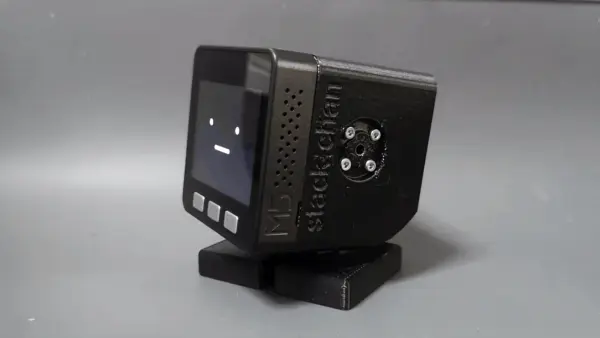
Stack-chan
$1301,382 stars on GitHub. Stack-chan — Palm-Sized Companion Robot Stack-chan is a palm-sized, open-source companion robot driven by an M5Stack microcontroller and JavaScript firmware. Created by Shinya Ishikawa, Stack-chan sits on your desk, turns its head to watch you, expresses emotions on its built-in display, and responds through speech. Source: https://github.com/stack-chan/stack-chan Capabilities Servo-driven head gaze/tracking Emotive faces (happy, angry, sad) + fully customizable face expressions Speech synthesis Composable behaviors ("mods") — mix and layer: expressions, tracking, speech, M5Unit addon support Programmable in JavaScript on the Moddable SDK (embedded JS framework; no C/Arduino required) Servo Paths — Pick Before You Print Two mutually exclusive configurations that change both the case geometry and electronics: | Path | Servos | Notes | |------|--------|-------| | PWM | SG90 / MG90S | Simpler, cheaper, standard hobby servo wiring | | Serial TTL | RS30X series | Smoother motion, requires a buffer IC and serial-servo case geometry | Picking a path determines which STL set and which PCB you build. Build Notes Requires a custom PCB — order Gerbers from JLCPCB/PCBWay ( directory in the repo) Modular 46-part printable enclosure (shell, bracket, feet, spacer, accessories: hat, backpack variants, Lego adapter) An official commercial M5Stack version (StackChan) is available; the open-source org fork is the reference for DIY Metadata GitHub stars: 1,382 Author: Shinya Ishikawa & community License: Apache 2.0 Links Firmware () STLs () Schematics + PCB () Roadmap Demo video (YouTube, EN subs)
 Other Robots
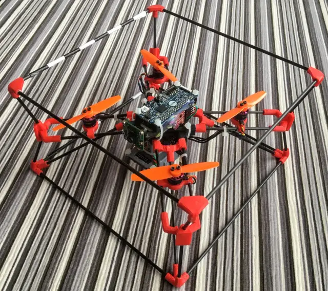
CogniFly — Foldable Collision-Resilient Nano Drone
$200CogniFly is an open-source, foldable, collision-resilient nano/micro quadcopter UAV with a soft exoskeleton inspired by insect morphology. The frame is assembled from 3D-printed flexible TPU parts and rigid PLA parts, connected by carbon fiber or bamboo strut rods that act as energy-absorbing springs on impact. At under 250g, it carries a Raspberry Pi Zero W for autonomous flight, a flight controller running INav/BetaFlight, and supports optical flow, lidar altitude hold, and camera-based computer vision. The collision-resilient design allows the frame to flex and absorb crash energy, making it ideal for research in cluttered or GPS-denied environments. The frame ships in multiple design generations; the Latest folder contains the current canonical PLA + TPU parts. All red-colored parts in the renders are TPU 95A (flexible). The only part requiring print supports is . Strut lengths: 8× 195mm (outer cage), 8× 97mm (arms), 4× 72mm (legs). Attribution Author: thecognifly (Ricardo de Azambuja et al.) GitHub: https://github.com/thecognifly/CogniFly-STL Project site: https://thecognifly.github.io/ License: See repository (research/academic project) Source repo: https://github.com/thecognifly/CogniFly-STL
 Mobile Robots
SpotMicro ESP32
$130377 stars on GitHub · michaelkubina/SpotMicroESP32 SpotMicroESP32 is Michael Kubina's redesign of the SpotMicro quadruped, derived from KDY0523's original Thingiverse design, optimized for support-free 3D-printing and built around an ESP32-DevKitC. 12-DOF (3 servos per leg). Source: https://github.com/michaelkubina/SpotMicroESP32 SpotMicro family — pick your compute target: | Variant | Controller | ROS | |---------|-----------|-----| | SpotMicro (Pi) — mike4192 | Raspberry Pi | ROS Kinetic | | SpotMicro Jetson Nano | Jetson Nano | ROS Melodic | | SpotMicro ESP32 (this) | ESP32-DevKitC | No ROS | Hardware: 12 servos (3 per leg: shoulder yaw, upper, lower) ESP32-DevKitC main controller Optional ESP32-CAM for vision LiPo battery with custom mounting brackets Software ecosystem (community forks): Maarten Weyn BLE/IK firmware: https://github.com/maartenweyn/SpotMicroESP32 Blacksheep Nitro Fork (PCB + walking gait + RC): https://github.com/Blacksheep909/SpotMicroESP32-Nitro-Fork SpotMicro-Leika (FreeRTOS + 2 gaits): https://github.com/runeharlyk/SpotMicroESP32-Leika SpotMicroAI Community: https://spotmicroai.readthedocs.io/ Resources: Thingiverse: https://www.thingiverse.com/thing:4559827 Original SpotMicro by KDY0523: https://www.thingiverse.com/thing:3445283 Printing SpotMicro is a 12-DOF quadruped — 4 legs, 3 servos each — so the shoulder and limb parts must be printed once per leg (×4), and the chassis side is printed as a left/right pair (×2). This is the support-free Kubina redesign, so no supports are needed. Print quantities: ChassisSide ×2; FrontCover ×1, RearCover ×1, Cameramount ×1. Per leg (×4 each): BottomShoulder, InnerShoulder, OuterShoulder, LimbBallBearingMount, LimbBottomShell, LimbTopShell, LimbServohornMount, FootTip. Note on RearCover: the file is labelled a "Template." It is a customizable base cover meant to be edited (e.g. to add a cutout for your specific electronics/port layout) before printing, rather than a fixed final part — print it as-is if you don't need a custom opening. The upstream source also includes many experimental and alternate variants (different power-board mounting plates, optimized covers, mold parts); those are optional alternates and are intentionally excluded from this set, which is one clean buildable SpotMicro.
 Arm Robots
SO-101 Teleop Arm
$359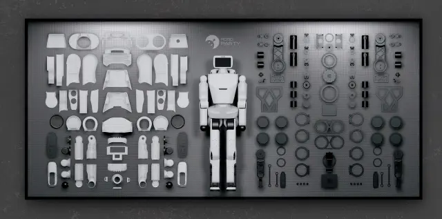 Humanoid
ROBOTO_ORIGIN Humanoid
$6960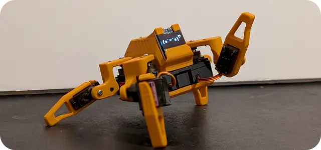 Mobile Robots
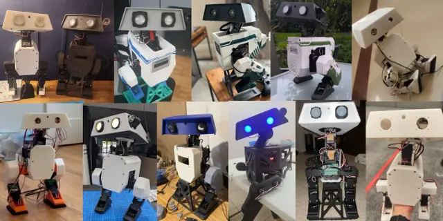
Sesame Quadruped
$851,619 stars on GitHub. Sesame is an affordable, open-source mini quadruped robot powered by an ESP32 microcontroller. Designed by Dorian Borian, Sesame uses 8 MG90S metal-gear servos (two per leg) for 8-DOF locomotion and features a 128×64 OLED display that serves as an expressive robot face. Source: https://github.com/dorianborian/sesame-robot All mechanical parts are fully 3D-printable on a standard FDM printer. The hardware folder contains both parametric STEP and Fusion 360 source models alongside the STL files, allowing full customization. The frame, internal structure, covers, and leg segments are all available as individual STLs. The ESP32 firmware handles inverse kinematics, face animations on the OLED display, and a WiFi-based control interface accessible from any browser. A desktop companion app (Sesame Studio) is included for easy gait configuration and pose tuning without writing code. Community documentation covers full assembly with detailed wiring diagrams and a comprehensive BOM. Hat variants are available (enclosed, open, cat ears) for personality customization. With over 1600 GitHub stars, Sesame has become a go-to beginner quadruped platform. License: Apache 2.0.
 Camera Bots
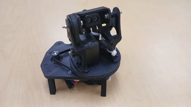
vdar — 3D LiDAR Scanner
$100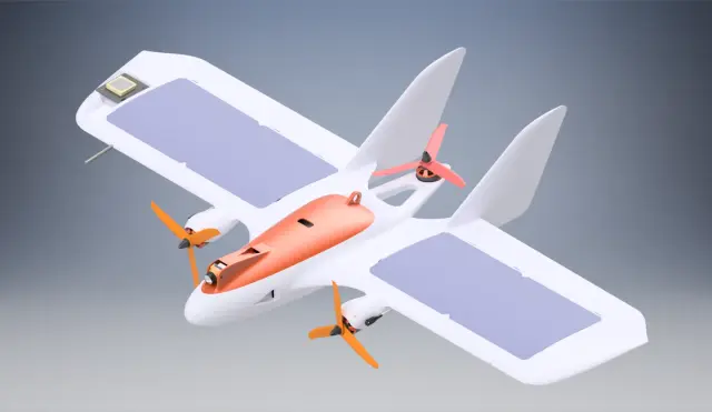 Other Robots
MiniHawk-VTOL
$200The MiniHawk-VTOL is a fully 3D-printed tricopter/fixed-wing hybrid VTOL aircraft designed by Steve Carlson. It uses three brushless DC motors — two tilting front motors for forward flight and yaw control, and one fixed rear motor for hover — plus four servos for elevon control surfaces and motor tilt. The 800mm wingspan plank-style airframe weighs ~460g printed in PLA, with a total all-up weight of 1000–1200g. Designed for ArduPlane/ArduPilot firmware, it supports R/C, FPV, and autonomous UAV experimentation. Attribution Designer: Steve Carlson (StephenCarlson) License: CC-BY-NC-SA 4.0 Source: https://github.com/StephenCarlson/MiniHawk-VTOL Project Page: https://hackaday.io/project/175286-minihawk-vtol
 Humanoids
Open Duck Mini
$14002,642 stars on GitHub. Open Duck Mini — Bipedal BDX Droid Replica Source: https://github.com/apirrone/OpenDuckMini A miniature bipedal character robot inspired by Disney's BDX droid (the little star of the Galactic Starcruiser walkabout e...
 Other Robots
Stringman
$210Room scale cable driven parallel robot
 Humanoids
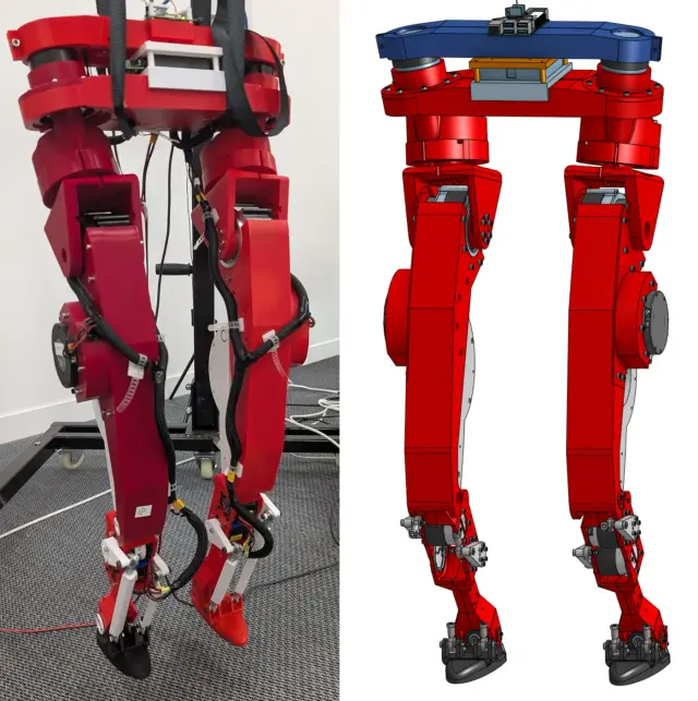
LeRobot Humanoid (Biped Platform)
$2600The LeRobot Humanoid (Biped Platform) is a fully open-source, 3D-printed humanoid biped robot developed by Virgile Batto and the Hugging Face LeRobot team. Powered by a Raspberry Pi 5 and 12 RobStride CAN-FD actuators arranged across two legs (6 degrees of freedom per leg, 12 DOF total), it represents a serious open-hardware effort to make capable humanoid locomotion accessible to researchers and advanced builders worldwide. Every mechanical, electrical, and firmware artifact is freely available under the Apache 2.0 license, from the Onshape CAD source to the bill of materials to the motor commissioning scripts. Creator & License Author: Virgile Batto (Hugging Face LeRobot team) License: Apache 2.0 Hardware repository (CAD, BOM, assembly docs, STLs): https://github.com/Virgileboat/lerobot-humanoid-hardware Runtime repository (motor control, gait, model inference): https://github.com/Virgileboat/lerobot-humanoid-runtime Public Onshape CAD document (start here for design exploration): https://cad.onshape.com/documents/fb645318a27646d1d8840be6/w/d1cae8805fb652b4d1614997/e/804a1da43f242001a05129b4 All build assets — STL files, BOM CSVs, wiring diagrams, motor commissioning scripts — are republished here under the same Apache 2.0 terms. Printing The Print All set is complete — all 47 unique STLs for one full biped. Both legs are present as proper left/right mirror pairs ( = left, = right). There are no missing parts and no alternates to deselect. The build uses ~75 printed pieces from these 47 files because several parts repeat. Until per-file print-multiples are supported, print the quantities below: Print x4 each (bearing spacers, shared across both legs): , , , Print x2 each (repeated per leg / both u-joints): , , , , , , , , , , , Print x1: every other file (the remaining torso, hip, femur and tibia parts — each left/right mirror is its own file). Total: 47 files → ~75 physical parts (3–4 kg PLA+). Left and right parts are true mirrors and not interchangeable. Hardware Requirements This robot is BYOD (Bring Your Own Device). The orobot-firmware layer does not currently support RobStride CAN-FD actuators; all joint control runs directly on the Raspberry Pi through the lerobot-humanoid-runtime repository. The orobot program record here serves as a build reference, asset hub, and control-interface stub. Required hardware: Raspberry Pi 5 (8 GB recommended) — primary compute SAVVYCANFD 2CH CAN-FD adapter (USB, dual channel, 12 Mbps max) — connects Pi to motor bus 12 × RobStride actuators: 2 × RobStride O0 (torso/hip yaw) 2 × RobStride O2 (hip Z) 4 × RobStride O3 (thigh) 4 × RobStride O5 (shin) IMU: BNO055 or BNO085 breakout board Mechanical: ~75 custom 3D-printed PLA+ parts, plus precision bearings and fasteners per BOM Specifications | Parameter | Value | |-----------|-------| | Degrees of freedom | 12 (6 per leg) | | Actuators | 12 × RobStride (CAN-FD) | | Estimated print weight | ~3–4 kg PLA+ | | Estimated total cost | ~$2,636 USD | | Skill level | Advanced | | Build time | Multi-week (motor commissioning → print → assembly → wiring → bring-up) | | CAD source | Onshape (public, link above) | | Control protocol | RobStride CAN-FD over USB adapter | Build Start Sequence Order long-lead items (motors, bearings, shoulder screws from ) first — they can take weeks. Print STLs per (~3–4 kg PLA+; orientation matters for structural leg parts). Commission and ID every motor before any mechanical assembly — protocol or ID errors after assembly require disassembling the leg to fix. Full step-by-step at lerobot-humanoid-hardware. Safety > High-torque actuators — a physical E-stop is required and must be accessible at all times during powered operation. See for the full bring-up checklist. Attribution This program page was created by the orobot BROKER-2 index to help builders find and start this project. All design credit goes to Virgile Batto and the Hugging Face LeRobot team. Please star the source repos if this build helps your project.
 3D Printers
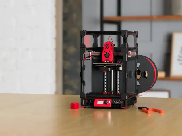
Voron 0.2
$550Voron Zero is a compact, fully-enclosed CoreXY 3D printer designed for high-speed, high-quality printing in a small footprint. The V0.2 revision is the official release maintained by Voron Design. Highlights 120 × 120 × 120 mm build volume CoreXY motion system Low-mass direct-drive extruder (Mini Stealthburner) Fully enclosed chamber 24V DC heated bed Klipper firmware Filament runout sensor Sensorless homing What's in this program Full STL set for the V0.2r1 revision (134 printed parts) Pointer to the official assembly manual PDF Klipper firmware configuration profile BOM via the Voron Configurator Build notes Most first-timers buy a complete kit rather than sourcing à-la-carte — LDO (~$800), Formbot (~$550), and Fysetc are the common choices. À-la-carte Misumi sourcing runs $400–600 but requires more lead time. Use the Voron Configurator to generate an accurate BOM for your region. The Voron community provides an interactive Printed Parts Guide and an active Discord for build support. Expect a multi-weekend build for first-timers. Links Voron-0 GitHub (STLs + manual) Official Assembly Manual PDF Voron Configurator (authoritative BOM) Printed Parts Guide Voron Discord Klipper firmware docs Source: https://github.com/VoronDesign/Voron-0 (GPL-3.0)
 Mobile Robots
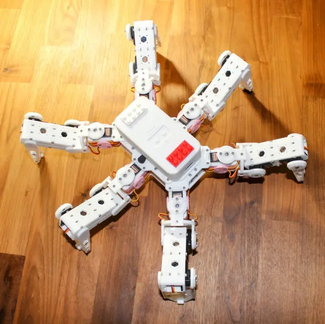
Hexapod
$120Hexapod — 3D Printed Six-Legged Walking Robot A fully 3D-printed hexapod robot with 18 servo motors (three per leg) providing lifelike, agile locomotion. Designed by rookidroid.com, this project uses either an ESP32 or Raspberry Pi Pico W/2W controller board with built-in WiFi for wireless remote control. The firmware supports over-the-air (OTA) updates so you can iterate on motion patterns without touching the hardware. Hexapod v2 is the recommended build. The original v1 used MG90S servos which are prone to failure; v2 upgrades to stronger 21G DS Power/Miuzei servos and is significantly more reliable. Do not use MG90S. Note: The controller board is proprietary to rookidroid.com. A generic ESP32 dev board can substitute — check the firmware docs for pin mapping. Specifications | Property | Value | |----------|-------| | Legs | 6 | | Servos | 18 x 21G (3 per leg: hip, knee, ankle) | | Controller | ESP32 or Raspberry Pi Pico W/2W | | Communication | WiFi (UDP port 1234) + OTA updates | | Power | 2 x 18650 Li-ion cells | | Printed Parts | 20 STLs, all print without supports | | Print time | ~40–60 hours total | | Skill level | Intermediate | Motion Modes The ESP32 firmware implements a pre-computed look-up-table gait system with 18 motion modes including: directional walking at 0, 45, 90, 135 degrees (left and right variants), 180 degrees; fast forward and backward; turn left and right; climb forward and backward; body rotations on X, Y, Z axes; and a twist mode. Attribution Creator: rookidroid.com Source: https://github.com/rookidroid/hexapod License: GNU GPL v3 Printing This is a complete, modular set of 20 unique parts. Because the hexapod has 6 identical legs (each with 3 joints), many parts must be printed in multiples. Per the upstream build guide, print the following quantities: Body (print once each): bodybase ×1, bodytop ×1, bodytopcover ×1, bodybattery ×1. Body (print in pairs): bodyside ×2, bodyfrontback ×2. Servo brackets (one per leg): bodyservoside1 ×6, bodyservoside2 ×6, bodyservotop ×6. Legs and joints (per-leg multiples): jointbottom ×12, jointtop ×12, jointcross ×6, legbottom ×6, legtop ×6, legside ×12. Feet (one set per leg): footbottom ×6, foottop ×6, footground ×6, foottip ×6. Optional: accessorycableholder ×1 (a cable-management add-on, not required for the robot to function). No supports are needed — orient each part as shown in the upstream print thumbnails. All 20 files are the correct, current parts; there are no duplicates, alternates, or version variants to choose between.
 Mobile Robots
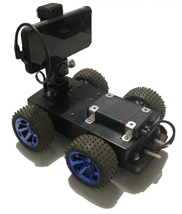
OpenBot
$503,262 stars on GitHub · MIT · Intel Labs + TU Munich OpenBot turns your smartphone into the brain of a low-cost robot — anyone with an Android or iOS device and ~$50 budget can build a capable AI-powered robot. Source: https://github.com/isl-org/OpenBot The robot body is a 3D-printed differential-drive chassis holding two gear motors, a speed controller, and a custom PCB — all controlled by an Arduino Nano. The smartphone docks on top, providing the camera, CPU, and network stack. Your phone's neural engine runs person-following, autonomous navigation, and custom AI policies via the companion app. 4 body variants + phone mount — regular (two-part top/bottom), block (PCB stack), glue (no-screw assembly), slim (narrow). See Print Files for the full set. The project also supports tank, MTV off-road, and RTR RC-chassis variants. --- Install Notes OpenBot's intelligence lives in the Android/iOS app — vision, navigation, data collection, and AI inference all run on the phone. The orobot device code only bridges the Arduino Nano motor controller layer (forward/backward/turn via serial JSON). Higher-level behaviors (person following, autopilot, data recording) require the OpenBot app connected to the Arduino via USB OTG cable. The orobot integration is useful for basic motor testing and manual drive, but does not replicate the full OpenBot feature set.
 Mobile
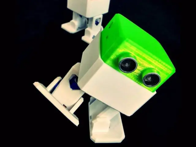
Otto DIY
$64Otto DIY — Bipedal Walker Robot Otto is one of the most beloved open-source DIY robots: a small bipedal walker that anyone can build with a 3D printer, an Arduino Nano, and four micro servos. Originally created by the Otto DIY community, Otto can walk, turn, dance, sing, and emote with optional ultrasonic, sound, and LED matrix add-ons. This Program is a learning interface for the Otto DIY platform. Full hardware control runs on the Arduino firmware in the source repo below. The orobot.io control sandbox lets you experiment with the command surface before wiring it into your own Otto. Specs | Property | Value | |----------|-------| | Type | Bipedal walker | | Servos | 4 × SG90 micro servo (LeftLeg, RightLeg, LeftFoot, RightFoot) | | Controller | Arduino Nano (also Uno, Micro, Mega, ESP8266, ESP32 in dev) | | Height | ~12 cm | | Estimated cost | $50–75 (core build) / $80–110 (with sensors) | | Estimated build time | 2–6 hours | | Skill level | Beginner / Intermediate | Source Repo: https://github.com/OttoDIY/OttoDIYLib (canonical Arduino library, v13.0) STLs + assembly guide: https://www.ottodiy.com/ Library examples: https://github.com/OttoDIY/OttoDIYLib/tree/master/examples Otto Blockly / app: https://www.ottodiy.com/#app Author: Otto DIY community License: GPL v3 (code) + CC-BY-SA 4.0 (mechanical design) Hardware integration status Otto runs on Arduino Nano with the OttoDIYLib firmware. orobot-firmware does not yet have Arduino Nano support — this Program provides the learning interface and command surface. To run a real Otto, flash OttoDIYLib onto your Arduino directly and use the bundled examples (, ). Capabilities Walk, turn, jump, moonwalk dance, ~10 named gestures (Happy, Sad, Angry, Love, Confused, Wave, Magic, Fail, Sleeping…), and 19 built-in songs. Full API in the OttoDIYLib examples. Credits Massive thanks to @JavierIH, @Obijuan, @sfranzyshen, and the dozens of contributors who have built and maintained Otto DIY for nearly a decade. Otto is one of the projects that proved tiny, friendly, accessible robots could be a global open-hardware movement.
 Mobile Robots
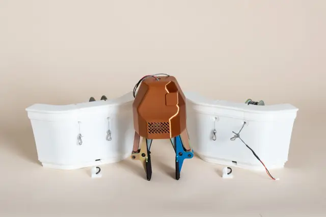
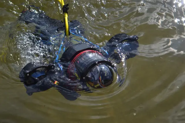
Underwater Drone
$105075 stars on GitHub. This open-source customisable underwater drone is a 3D-printable submersible robot designed by Guido and Fabio Schillaci at Humboldt-Universitat zu Berlin. Published as an arXiv preprint, the design enables multiple propeller and thruster configurations for varying research and exploration tasks. Source: https://github.com/guidoschillaci/underwater-drone The drone is built around the 4" watertight enclosure sold by BlueRobotics, providing a waterproof housing for electronics. Thrusters use brushless motors (see note below on component versions); all 18 structural components are 3D-printable and recommended to be printed with solid infill for watertight structural integrity. The modular clamp system allows configuring the drone for different mission profiles — forward-facing cameras, lateral thrusters, ballast placement, or instrument mounting. See Print Files for the full list of 18 printable components. Thruster note: the description references Turnigy Aerodrive DST (DST-700/DST-1200) brushless motors; some BOM links point to the ApisQueen 5060 Waterproof Brushless Underwater Motor instead. Verify which motor you are sourcing before purchase — the two are not the same form factor. Applications include aquatic research, underwater exploration, coral reef monitoring, and educational robotics. License: Creative Commons Attribution 4.0 International (CC-BY 4.0). --- Install Notes This repository contains CAD files and assembly instructions for a 3D-printable submersible — there is no firmware or control software included. The design is intended for custom electronics integration. The orobot Program code is a reference stub only. To build a controllable version, you will need to design or source your own motor controller and connect it via serial or WiFi. Build Guide 3D models, build instructions, and configuration details: github.com/guidoschillaci/underwater-drone --- Printing This Print All set maps 1:1 to the upstream folder — all 18 structural components, no sim meshes or duplicates. Print in PETG (hydrolysis-stable) with solid / near-100% infill for watertight structural integrity. Quantities (4-thruster configuration) The drone uses 4 thrusters, so thruster and propeller parts repeat: | Part | Qty | Notes | |------|-----|-------| | thrustermain.stl | 4 | One per thruster | | thrustercap.stl | 4 | One per thruster | | thrustermotormount.stl | 4 | One per thruster | | thrusterdst2bluerovadapter.stl | 4 | Motor-to-housing adapter (one per thruster) | | propeller.stl | 4 | One per thruster (or use motor-matched commercial props per BOM) | | clampanteriorsuperior.stl | 1 | Modular clamp | | clampanteriorinferior.stl | 1 | Modular clamp | | clampposteriorsuperior.stl | 1 | Modular clamp | | clampposteriorinferior.stl | 1 | Modular clamp | | posteriorclamp2tubeconnector.stl | 1 | Clamp-to-tube connector | | rearclampconnector.stl | 1 | Rear clamp connector | | adapter90.stl | 1+ | Tube adapter | | adapterroundmale.stl | 1+ | Tube adapter | | adapterroundfemale.stl | 1+ | Tube adapter | | adaptersplit.stl | 1+ | Tube adapter | | stick.stl | 1+ | Structural rod | | ballastcylinder.stl | 1+ | Ballast tube | | ballastcap.stl | 1+ | Ballast cap | Modular by design: the clamp/adapter/ballast system is meant to be reconfigured for different mission profiles (forward camera, lateral thrusters, ballast placement). Print extra adapters, sticks, and ballast cylinders to suit your chosen layout — the counts above are a baseline for a standard 4-thruster build. Motor note: the upstream design targets Turnigy Aerodrive DST motors (hence ); if you source the ApisQueen 5060 motor listed in some BOM links, the motor-mount fit differs — verify before printing the thruster mounts.
 Arm Robots
PAROL6 Desktop Robot Arm
$350PAROL6 Desktop Robot Arm A high-performance 6-DOF desktop robotic arm designed to mirror industrial robots in mechanical design, control software, and usability — but small enough to sit on your desk. Designed by Petar Crnjak (Source Robotics). Released under GPLv3. STL files, control software, and GUI are all open-source. What you can do Run kinematic demos from your browser Practice pick-and-place with the included gripper attachments Learn industrial-style arm control (home, jog, teach points) Extend with your own gripper tooling (pneumatic, vacuum, 2-finger) Specs | | | |---|---| | Degrees of Freedom | 6 + gripper | | Joints | J1 base, J2 shoulder, J3 elbow, J4/J5 forearm, J6 wrist | | Payload | ~500g (typical) | | Reach | ~400mm | | Controller | Custom PAROL6 control board (STM32-based, PlatformIO) | | Motors | NEMA 17 stepper motors on joints | | License | GPLv3 (software + STLs) | Build options Two paths: 1. Buy a kit from Source Robotics — fully supported, pre-sourced parts 2. Source & print yourself — follow the BOM and Building instructions STL files This program includes a representative subset of 12 STLs covering BASE, SHOULDER, ELBOW, FOREARM, GRIPPER, and ESTOP groups. For the full 41-part canonical set (plus mounting plates and extras), see the STL directory on GitHub. Resources 📖 Official Docs 🎥 YouTube demo 🐍 Python API 🎛 Commander software 🤖 ROS2 / MoveIt simulation 💬 Discord community ⚠️ Safety PAROL6 involves lethal voltages and moving mechanical parts. Read the full SAFETY WARNING AND DISCLAIMER before assembling or operating. Attribution Source: PCrnjak/PAROL6-Desktop-robot-arm · License: GPLv3 · © Petar Crnjak / Source Robotics Printing PAROL6 is a 6-DOF desktop robot arm. The Print All set covers the full mechanical build: the base/electronics enclosure, the J1 turret/shoulder assembly, the J2 upper-arm joint, the upper arm and its covers, the elbow (J3/J4), the forearm and J5 wrist drive (pulleys, belt lids), the wrist, the E-stop housing, and a gripper attachment. Print one of each part. Most belts/pulleys are printed once; follow the upstream assembly guide for orientation and supports. Gripper options: this set includes GripperARMS plus the pneumatic and vacuum gripper holders as alternate end-effectors — choose the one that matches your hardware (you don't need all three). A second "horizontal pneumatic" gripper variant exists upstream and can be substituted if preferred. Important — one oversized part: the main "Upperarm.STL" (~33 MB) is the single largest part and exceeds this site's file-size limit, so it could not be hosted in the Print Files list. Download it directly from the upstream repository (PCrnjak/PAROL6-Desktop-robot-arm, under STL/UPPERARM/Upper_arm.STL) and print it alongside the parts here. Every other structural part of the arm is included.
 Arm Robots
SO-ARM101 Standard Open Arm
$174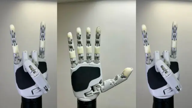 Grippers
Aero Hand Open
$314Aero Hand Open is an open-source, tendon-driven robotic hand designed by TetherIA for dexterous manipulation research. Unlike expensive proprietary solutions, this hand focuses on simplicity, reliability, and accessibility — fully 3D-printed structure with off-the-shelf electronic components. Key Specs: 7 DoF | 16 joints | 5 fingers | 389g | ESP32-S3 controller | 7× Feetech HLS3606M servos Attribution: TetherIA Inc. — https://github.com/TetherIA/aero-hand-open License: Design files (CAD/STL/BOM/docs) — CC BY-NC-SA 4.0 | Software (firmware/SDK) — Apache-2.0 Source: https://github.com/TetherIA/aero-hand-open Docs: https://docs.tetheria.ai | Shop: https://shop.tetheria.ai Printing This is a single left hand (all parts are prefixed; the upstream repo also publishes a mirrored right hand under prefixes if you need the opposite hand). Structural / palm (1 each): leftbaselink — palm/chassis lefttlink — thumb carpometacarpal mount Five finger chains. Each of the four fingers (index, middle, ring, pinky) is a four-link chain; the thumb is its own four-link chain: Index: leftindexproximal / middle / distal / tip Middle: leftmiddleproximal / middle / distal / tip Ring: leftringproximal / middle / distal / tip Pinky: leftpinkyproximal / middle / distal / tip Thumb: leftthumbmcp / proximal / distal / tip Mount adapters (pick the one that matches your wrist/base — optional): 135degreesadapter — for a 135° angled mount threadedmountadapter — for a threaded base mount Print in PLA, 0.2 mm layer height, tree supports on the build plate only. Per the BOM, several small hardware items are not separate STLs: the 6× cable spools and the silicone finger pads are produced by other means (spools are integral / cast pads use Ecoflex 00-30 in a mold). Buy undersized 2x10 pins — standard 2x10 pins are too tight for the 2x5x2.5 mm bearings and cause joint stiffness. Route the tendons before final assembly of each finger module; retrofitting cables through assembled joints is extremely difficult. The full set is 24 STL files (22 hand parts + 2 optional mount adapters), driven by 7× Feetech HLS3606M servos.
Browse by type