3D Print Open Source AI Robots
 Robotic Hands
OpenBionics Prosthetic Hand
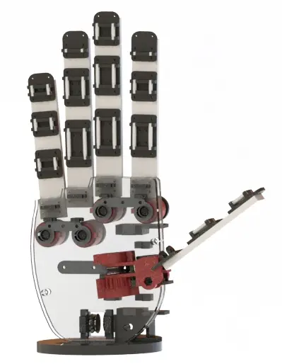
$200OpenBionics Prosthetic Hand A low-cost, 3D-printable, fully functional anthropomorphic prosthetic hand. The OpenBionics initiative (openbionics.org) publishes designs that cost under $200 and weigh under 300 g, aimed at closing the gap between commercial prosthetics (often tens of thousands of dollars) and what an individual or clinician can fabricate themselves. How it works The standout feature is a whiffletree-based differential mechanism. A single actuator drives all five fingers — but because of the differential, each finger stops independently when it contacts an object. That one trick unlocks 144 distinct grasp poses from a single motor, letting the hand conform to a wide range of objects (cylinders, pinches, key grips, hooks) without per-finger control. A set of small mechanical locks lets the user selectively block specific fingers, which is how grasp selection is done on the physical device — no complex EMG classifier required at minimum. What you get Fully printable 5-finger right hand (mirror files for left also available in upstream repo) HerkuleX DRS-0201 smart servo as the single actuator Wire-driven tendons with a differential bar mechanism Parametric CAD — scale the hand to fit different users using anthropometry tables Optional body harness + breakout board for integration with EMG or button control Canonical printed parts , — two-part palm shell , , , , — finger bodies (multi-phalanx each) — mount for the smart servo , , — the whiffletree differential — wrist interface The upstream repo contains ~280 STLs total covering left + right hands, the HDM variant, lockable mechanisms, and the wearable harness. What you can do with it Teleop grasping demos — use the orobot cloud surface to command preset grasps (open, power grip, pinch, tripod). EMG or button-driven control — the upstream Arduino code reads muscle signals or switches and triggers grasps. This program wraps that with a cloud-side trigger surface. Research platform — anthropomorphic, under-actuated, fully open — a good baseline for grasp planning, tactile sensor integration, and rehabilitation engineering projects. Education — the whiffletree differential is a genuinely elegant piece of mechanical design; students can print one in a weekend and understand underactuated grasping hands-on. Ethics note This is a research-grade design published for open study and community iteration. For clinical use as a medical prosthesis, local regulatory review, professional fitting, and ongoing care are required — 3D-printable ≠ ready to wear. Attribution & license Initiative: OpenBionics (openbionics.org) Upstream repo: https://github.com/OpenBionics/Prosthetic-Hands License: Creative Commons Attribution-ShareAlike 4.0 International (CC-BY-SA 4.0) Homepage: https://www.openbionics.org/ Links Upstream: https://github.com/OpenBionics/Prosthetic-Hands HerkuleX servo docs: see RobotShop product page (original dst-robot.com manual URL is no longer available) Project page: http://www.openbionics.org/ Build Guide Assembly guide and parts list: OpenBionics Assembly Guide Printing This is a curated 24-part subset of the OpenBionics upstream (which has ~280 STLs across left/right hands, the HDM variant, locks, and harness). It covers one complete right hand plus the optional control/wear modules. Print in ABS/PLA, ~304 cm³. Most parts are print-one-each; the fingers are individual (each is a multi-phalanx body). Core hand — print one each (14): palmDown, palmUp — the two-part palm shell index, middle, ring, pinky, thumb — the five finger bodies baseHerkulex — mount for the single HerkuleX DRS-0201 servo mainBar, barIndexMiddle, barRingPinky — the whiffletree differential bars (this is the mechanism that lets one motor drive all five fingers and conform to objects) BasePulleyInsidePalm, SupportPulleyPalmUpAssem — tendon-routing pulleys inside the palm FlangePlate — wrist interface Optional module — selectable finger locks (4): dovetailfemale, lockMechanismBracket, lockMechanismSupport, and the button hardware below let the user mechanically block individual fingers to pick a grasp. Print only if you want manual grasp selection. Optional module — button control (3): buttonAxle, buttonBase, buttonFrame — the physical button assembly for triggering/locking grasps without EMG. Optional module — wearable harness (4): HarnessEE, HarnessEntry, HarnessFemaleHole, HarnessMaleHole — the body-harness breakout for mounting the hand on a wearer. Print only for a worn build. Left hand: This list is the right hand. The upstream repo contains full mirror files for a left hand (and an HDM variant) — add those from the OpenBionics repo if you need a left hand instead. Not printed:** 1× HerkuleX DRS-0201 smart servo (the single actuator), elastic/Dyneema tendon cord, ball bearings, springs, and M2/M3 fasteners per the BOM.
 Arm Robots
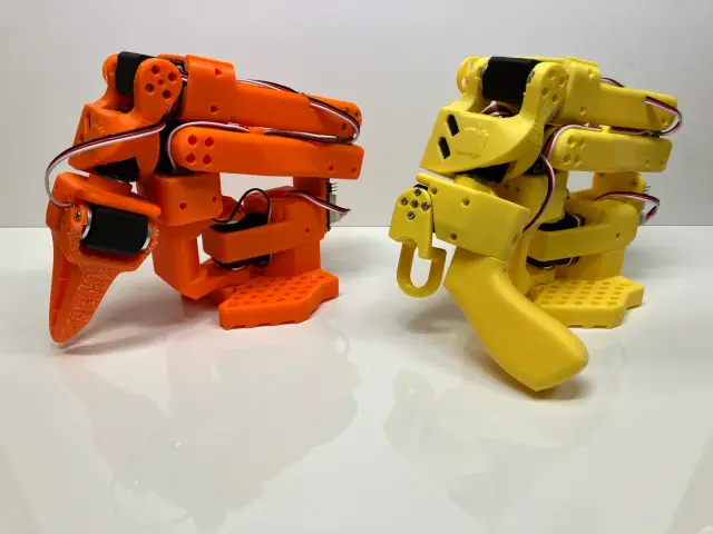
SO-101 Teleop Arm
$359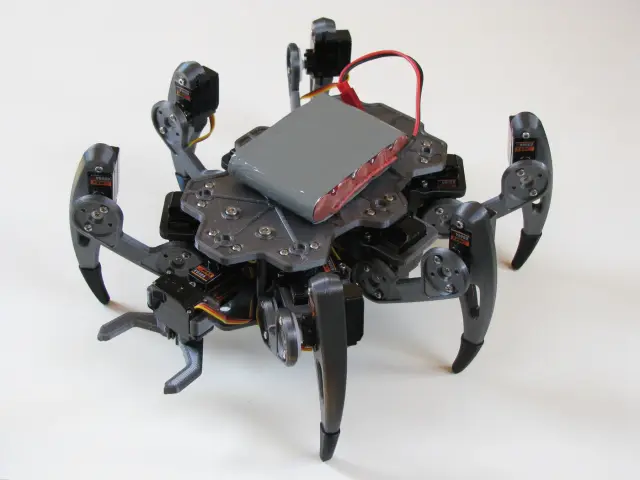 Mobile Robots
ZeroBug Hexapod
$220ZeroBug is a 3D-printed micro-servo hexapod from Maximilian Kern (CoretechR), designed as a compact, low-cost teaching platform for inverse kinematics, gait generation, and embedded locomotion control. Eighteen SG90-class hobby servos (three per leg) give the robot the full coxa-femur-tibia kinematic chain needed for smooth, 3D body pose control — the same degree-of-freedom layout used by commercial research hexapods at a fraction of the cost. The control architecture is the interesting bit. A Raspberry Pi Zero acts as the high-level brain and user-interface host: it serves a web dashboard (joystick, keyboard, multitouch, Bluetooth gamepad inputs) and streams MJPEG video from the Pi camera. An STM32F103 ("Blue Pill") board handles the real-time dirty work — inverse kinematics for all 6 legs, tripod/wave gait generation, and the 18 servo PWM channels — because running those loops reliably on Linux is a losing battle. The Pi and STM32 communicate over UART with a simple framed protocol. This "dumb but real-time microcontroller + smart but latency-tolerant SBC" pattern is a great template for any Pi-based locomotion robot. The included front 2-finger gripper makes ZeroBug unusual among hobby hexapods — most are pure walkers, but ZeroBug can actually pick up objects. This opens up simple mobile-manipulation demos: walk to a target, pose-align the body, grab, carry, release. This program exposes cloud-side locomotion endpoints (directional walk with speed, yaw turn, full 6-DOF body pose, wave animation, gripper open/close, emergency stop) that relay to the Pi Zero's web backend over WebSocket, which in turn commands the STM32 over UART. Credit to Maximilian Kern (CoretechR) — upstream repository at https://github.com/CoretechR/ZeroBug under GNU GPLv3. Full build log at coretecrobotics.de. Printing All 10 STL files match the upstream CoretechR/ZeroBug set 1:1 — the list is already correct and complete. Note the print quantities, since the static Print-All set lists each file once: Per-leg parts (print x6 — once per leg): , , , . ZeroBug is a 6-leg hexapod with an identical coxa-femur-tibia-foot chain on every leg, so each of these is printed six times (18 leg segments + 6 feet total). Body (print x1): and form the two-part central chassis that sandwiches the electronics. (print x6+): servo-mount / joint spacer; print at least one per leg (six), more if you want spares — small part. Front gripper (print x1 each): , plus the mirrored jaw pair + (both required — they are left/right mirrors, not alternates). The gripper is optional if you only want a walker, but it is the feature that distinguishes ZeroBug from typical hobby hexapods. No duplicates, simulation meshes, alternates, or assembly-reference blobs are present. Servos (18x MG90S-class), the Raspberry Pi Zero, STM32F103, camera, battery, and electronics are sourced from the BOM — not printed.
 Arm Robots
PingTi Arm
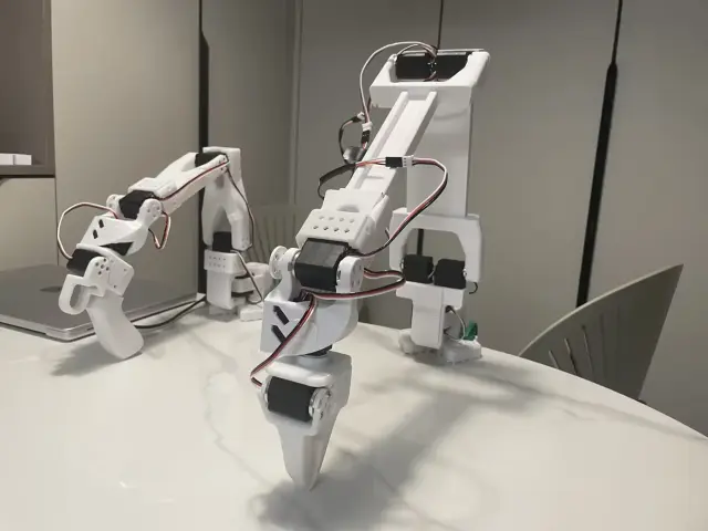
$150PingTi Arm is an open-source, human-scale robotic arm built for affordability and compatibility with the SO-ARM100 ecosystem. Its name comes from the Chinese "平替" (píng tì), meaning "affordable substitute" — the arm delivers human arm proportions at a fraction of typical robot arm costs. Designed to be fully compatible with Hugging Face's LeRobot framework, PingTi Arm supports teleoperation, imitation learning data collection, and policy deployment out of the box via the pingtilerobotbridge SDK. Key specs: Reach: 600mm arm span (excluding end effector) Payload: Up to 500g at full extension Joints: 6 DOF: base yaw, dual-motor shoulder pitch, elbow pitch, wrist pitch, wrist roll + gripper Servos: STS3215 Feetech serial bus smart servos (same family as SO-ARM100) Build cost: ~$261 single arm | ~$390 leader-follower pair SO-100 upgrade path: If you already own an SO-100 arm (12V, 30kg.cm variant), you only need 2 additional servos + a USB drive board (~$157) to assemble PingTi Simulation: Full URDF and collision meshes included for MuJoCo/Isaac Sim Why human-scale? Most low-cost robot arms (SO-100, Koch v1) are tabletop-scale. PingTi Arm's 600mm span covers real desktop-manipulation tasks — grasping objects at the edge of a table, pouring, stacking — that shorter arms can't reach without repositioning. LeRobot integration: Connect PingTi Arm as a follower in a leader-follower teleoperation setup using SO-100 as leader. Record demonstrations, train ACT or Diffusion Policy, and deploy. The pingtilerobotbridge repo provides all the calibration and control scripts. Hardware and software licensed under Apache 2.0. Original design by nomorewzx — https://github.com/nomorewzx/PingTi-Arm Printing This list contains the 12 STL parts from the official PingTi Arm folder — exactly what's needed to print one single arm. Printed in PETG (Bambu A1 reference), 0.2mm layers, 13% infill, supports on. ~600g filament, ~20 hr total. Print one of each (10 required parts): baselinkfromso100.stl, baselinkidleclampfromso100.stl, baselinkservomountframefromso100.stl — base assembly (these three are reused from the SO-100 design) baseyawlink.stl — base yaw joint shoulderlink.stl — shoulder extension link elbowlink.stl — elbow extension link wristpitchlinkfromso100.stl, wristrollfromso100.stl, wristservomountframefromso100.stl — wrist + gripper assembly (reused from SO-100) movinggripperfromso100.stl — gripper jaw Optional alternates (2): shoulderlinkalternate.stl and elbowlinkalternate.stl are slightly shortened versions of the shoulder/elbow links designed to print flat (horizontally) on a Bambu A1 bed, mimicking the SO-ARM101 design. Print these instead of the standard shoulderlink/elbowlink if your bed can't fit the taller standard links — not in addition. Note on "fromso100" parts: The suffix only means the design file was copied unchanged from the SO-100 repo. They are still required prints for every PingTi build — this is a single build path, not a separate variant. The "SO-100 upgrade path" mentioned in the specs refers only to reusing servos/control board you may already own (you still print all the same parts). Removed from the previous list: simulation/URDF meshes ( duplicates such as elbowlink1, shoulderlink1, movinggripper1, wristlink1, grippermount1, and the large sim baselink.stl) and the 8 STS3215 servo-body reference meshes — none of these are printed parts (the servos are purchased; sim meshes are for MuJoCo/Isaac visualization only). Servos (not printed):** 7× STS3215 — base yaw ×1, shoulder pitch ×2 (dual motor), elbow ×1, wrist pitch ×1, wrist roll ×1, gripper ×1.
 Robotic Hands
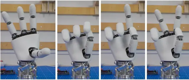
Amazing Hand
$150Amazing Hand is an open-source 8-DOF humanoid hand that packs all its actuators inside the palm — no cables, no deported motors, no forearm clutter. Derived from Pollen Robotics' expertise on Reachy 2, it brings professional-quality dexterity at under 200€. Four fingers, each with two degrees of freedom (flexion/extension and abduction/adduction), are driven by parallel mechanisms using pairs of Feetech SCS0009 micro servos. The result is a surprisingly expressive hand that can grasp, pinch, point, spread, and form complex gestures. Key specs: DOF: 8 (2 per finger × 4 fingers — index, middle, ring, pinky) Mechanism: Parallel mechanism per finger — both joints driven simultaneously by 2 servos Servos: 8× Feetech SCS0009 (serial bus, compact) Weight: ~400g assembled Build cost: Under 200€ (including servos) Wrist interface: Designed for Reachy 2's Orbita 3D wrist, adaptable to other platforms SO-ARM100 interface: Adapter STL included for mounting on SO-ARM100 Design philosophy: The parallel mechanism is the key innovation: two servos actuate each finger through a gimbal linkage, decoupling flexion/extension from side-to-side movement without requiring tendons or cables. All 8 actuators are housed within the palm housing, keeping the wrist clean and the arm kinematics unaffected. Control: Two modes: Python serial bus (using a Waveshare SC driver board) or Arduino + Feetech TTL Linker. Both methods and demo code are included in the repository. An "Amazing Hand Enhanced" branch extends this design with additional capabilities — see the repo for the latest. Code licensed under Apache 2.0. Mechanical design licensed under CC BY 4.0. Original design by Pollen Robotics — https://github.com/pollen-robotics/AmazingHand Printing This is a right hand (the upstream folder also ships mirrored palm/shell/plate/wrist parts if you want to build a left hand instead — swap the four parts below for their equivalents). Finger parts — print 4× each (one set per finger; the four fingers are identical): Amazing-Hand-Parts---Distal Amazing-Hand-Parts---DistalShell Amazing-Hand-Parts---Proximal Amazing-Hand-Parts---ProximalShell Amazing-Hand-Parts---FingerFrame-1 Amazing-Hand-Parts---FingerFrame-2 Amazing-Hand-Parts---Gimbal Amazing-Hand-Parts---Link That is 8 finger STLs × 4 = 32 finger prints. The two shell parts (DistalShell, ProximalShell) are intended to be printed in flexible filament (Filaflex 82A) for the fingertips/grip surfaces; the frames, gimbal, link, distal and proximal print in rigid PLA. Palm / wrist — print 1× each (right hand shown): Amazing-Hand-Parts---R-HandPlate Amazing-Hand-Parts---R-PalmShell Amazing-Hand-Parts---R-TopShell Amazing-Hand-Parts---R-WristInterface Linkage / mounting: BallJointRod---Spacer — print 1× (linkage spacer) SO-ARMInterface — optional; print 1× only if mounting the hand on a SO-ARM100 arm. The default wrist interface targets Reachy 2's Orbita 3D wrist. Total in this Print All set: 14 unique STLs, expanding to ~37 physical prints (32 finger + 4 palm/wrist + 1 spacer; SO-ARM adapter optional). Drives 8× Feetech SCS0009 servos (2 per finger). Note: the upstream BallJointRod LengthToolings part is an assembly jig for cutting the M2 rods to length, not a robot component, so it is excluded here — print it from the source repo only if you need the cutting guide.
 Robotic Hands
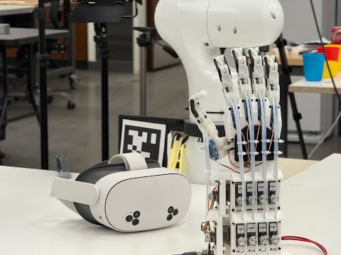
BiDexHand V4
$600BiDexHand is a 16-DOF biomimetic dexterous robotic hand that mimics the kinematic structure of a human hand — complete with independent adduction/abduction for each finger and a 4-DOF opposable thumb. The design uses a cable-and-pulley tendon system with 15 Feetech SCS0009 servos arranged in an N-configuration within the palm housing, plus a dedicated four-bar linkage for the DIP joint of each finger. The thumb has all four biomimetic degrees of freedom: CMC abduction/adduction, CMC flexion/extension, MCP abduction/adduction, and MCP flexion/extension. Key specs: DOF: 16 total — 3 DOF per finger (MCP ab/ad, MCP flex/ext, PIP flex/ext + coupled DIP) × 4 fingers, plus 4-DOF thumb Actuation: Cable-and-pulley tendon system, 15× Feetech SCS0009 servos + servo2040 controller Grasps: Power grasp, pinch grasp, precision manipulation, VR teleoperation VR control: Meta Quest motion shadowing via WebXR (separate VR teleop repo) Franka integration: Full-arm VR teleoperation with BiDexHand as the end effector ROS 2: Full ROS 2 Jazzy packages included (motion shadowing, servo streaming, CLI) Design: Open CAD on OnShape, STEP + STL files in repository V4 improvements over prior versions: Updated single-shear phalanx design (more durable under high-frequency grasping) Servo calibration modules for accurate joint position mapping Unified Feetech servo ecosystem throughout (SCS0009 everywhere) servo2040 PWM controller option alongside traditional SCS bus MIT License. Original design by Zhengyang Kris Weng — https://github.com/wengmister/BiDexHand Printing The print set is the 26-part hand from the upstream BiDexHand folder. BiDexHand has four identical fingers plus a distinct thumb, so several phalanx parts are printed in multiples — the static list shows each file once. Finger phalanx parts — print x4 (one set per finger): , , , , , , The four fingers (index, middle, ring, pinky) are mechanically identical, so each part is printed four times. Each finger is a 3-DOF unit (MCP ab/ad, MCP flex/ext, PIP flex/ext with a coupled four-bar DIP). Thumb — print x1 each (4-DOF opposable thumb, unique parts): , , , , , , Palm / housing — print x1 each: , , Servo sleeve & carriage (palm servo housing) — print x1 each: , , , , , , , Tendon pulley — print x15 (one per servo): — small SCS0009 cable pulley; the hand uses 15 Feetech servos, so print one pulley per servo. Cleanup note: the imported list previously held 46 files — the 26 real parts plus 20 duplicates that were the same parts re-imported under a second (double-underscore) naming scheme alongside the primary set. The duplicates were verified by byte-size match and removed, leaving the clean, complete 26-part set. Servos (15x Feetech SCS0009), the servo2040/ESP32 controllers, cabling (DuraBraid line, PTFE tube), bearings, springs, and McMaster pivot hardware are sourced from the BOM, not printed.
 Arm Robots
Pedro Robot Arm
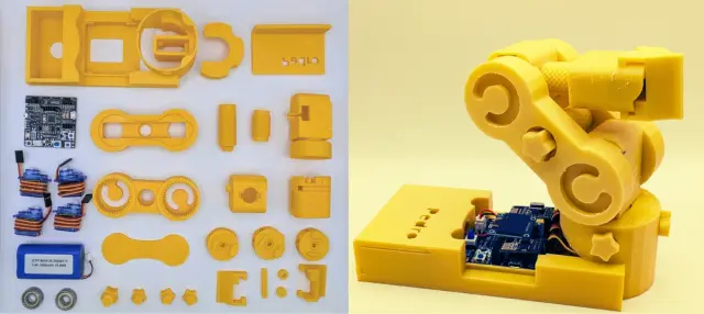
$40Pedro is a fully open-source, 3D-printable educational robot arm designed for STEM classrooms and makers who want to learn robotics from scratch. With only four printable parts, four mini servo motors, and tool-free snap-together assembly, Pedro can be built and operational in under 10 minutes.Design Philosophy Source: https://github.com/mattions/pedro Pedro is intentionally minimal. The entire structure consists of four 3D-printed components — BASE, ARM, GEAR, and SERVO bracket — that snap and gear together without screws or adhesive. This makes it ideal for workshops where dozens of students can assemble their own robot simultaneously. All parts print in under 2 hours on any FDM printer at 0.2mm layer height in PLA or ABS. Electronics Pedro is powered by a custom Arduino-compatible controller board called the Pedro Board, which integrates four servo outputs, an nRF24L01 radio module for wireless control, an HC-05 Bluetooth module for smartphone connectivity, and an ESP8266 for WiFi and IoT integration. Power comes from a 7.4V LiPo battery rechargeable via USB. Control Modes Pedro supports five control modes: Manual (serial/USB from a PC), Radio (nRF24L01 remote), Bluetooth (smartphone app), Replay (execute recorded sequences), and Record (capture and store movement sequences). The firmware is built on the Arduino platform and is fully open source under Apache 2.0 in the PedroRobot repository. Community Pedro is used in over 70 schools and educational workshops across France and internationally. The project ecosystem includes Pedro Board (PCB gerbers + schematics), PedroRobot (Arduino firmware), and PedroSTEM (complete lesson plans and activities). All repositories are published under Apache 2.0 by Almoutazar Saandi. Printing Print files match the upstream source repository (github.com/mattions/pedro, ) one-to-one — all nine parts are byte-identical to the repo. Structural parts (print 1 each): — base / shoulder servo mount — elbow servo mount — wrist servo mount — wrist joint — end effector / tool point , — remaining structural links (repo ships these under generic names) Mirror pair (print both, not alternates): + — the two halves of the forearm; both are required. Servos: 4 × Tower Pro SG90 9g micro servos (base, shoulder, elbow, wrist). The Pedro Board PCB (or an Arduino Uno/Nano substitute) and all electronics are sourced from the BOM, not printed. Cleanup note: Four extra files (, , , ) were removed — they are not present in the cited source repo, their byte sizes did not match any repo part (e.g. was an anomalous 7.6 MB), and the hero photo shows the multi-part repo design rather than the four-piece snap-together variant described in the older marketing text above. Keeping them would have over-printed parts from a different design.
 Humanoids
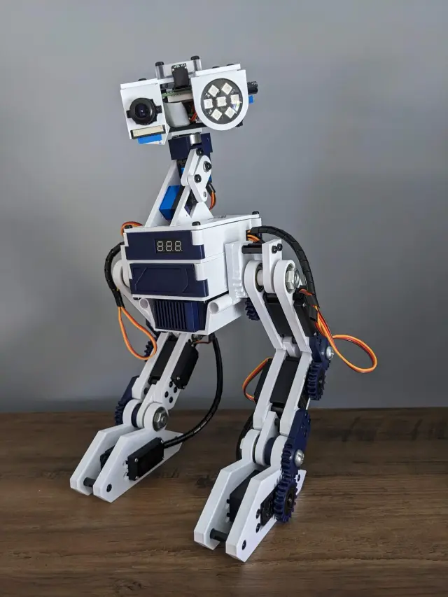
Modular Biped
$260467 stars on GitHub · MIT · MakerForge Tech / Aaron Mason The Modular Bipedal Robot is an open-source 3D-printable companion robot from MakerForge Tech / Aaron Mason, built around a Raspberry Pi + Arduino Pro Mini split. The repo includes the full STL set for the v2 body, head, neck, and legs, plus a modular Python/C++ software framework with drop-in modules. Source: https://github.com/makerforgetech/modular-biped Architecture: Raspberry Pi (Pi 4 or Pi 5) handles vision, speech, and orchestration Arduino Pro Mini handles real-time servo control via serial Custom PCBs for power and IO IMX500 AI camera module supported Software modules (drop-in): Vision/tracking: face/object detection, motion detection Speech/TTS: text-to-speech, Braillespeak LLM/translation: ChatGPT chat, language translation Peripherals: NeoPixel LEDs, buzzer, audio Connectivity: RTL-SDR radio, Viam integration, serial bus Build resources: Wiki & build guide: https://github.com/makerforgetech/modular-biped/wiki 3D-print files: https://github.com/makerforgetech/modular-biped/tree/main/3dprints/v2 Hardware list: https://github.com/makerforgetech/modular-biped/wiki/Hardware Software architecture: see Software Architecture.drawio.svg in repo License: MIT. Printing This is the coherent v2 print set. Modular Biped is an 8-servo bipedal robot (6 leg servos — hip/knee/ankle per side — plus 2 head servos). Print one of each part. The legs and feet are left/right mirror pairs (leftlegupper/rightlegupper, leftleglower/rightleglower, leftfoot/right_foot); both sides are required and are not alternates. The parts cover the skeleton, the front/back body case, the head (top, bottom, lid, visor), the neck/tilt mechanism, and the two legs with feet. Recommended print as drawn for the v2 design. Note: the upstream source includes a file named complete (with a matching complete preview image) — this is a full assembled model of the whole robot used for visualization, not an individual printable part. It has been removed from this Print All set so the list yields each part once rather than printing a fused copy of the entire robot.
 Mobile Robots
OpenQuadruped
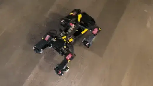
$350465 stars on GitHub. OpenQuadruped is an open-source 3D-printed quadruped robot by Adham Elarabawy, with 12-DOF Bezier-curve gait generation, full 6-axis body pose manipulation, and a custom 3DOF-leg inverse kinematics model that accounts for actuator offsets. Source: https://github.com/adham-elarabawy/open-quadruped Built around 12 servos (3 per leg: hip, upper, lower) on a custom PCB driving a Teensy controller. ROS infrastructure ties together the high-level gait planner, body IK, and Gazebo / RViz simulation. Hardware: 12-DOF Bezier-curve gait engine Custom 12-channel servo PCB (gerbers in repo) Teensy LLC for real-time servo dispatch Reinforced shoulder mounts (v2 redesign) What's in the repo: Full STL set: chassis, shoulders, legs, calibration jigs (hardware/3d-printing) Custom PCB gerber files (hardware/pcb) Teensy firmware (llc-teensy) Python control library + Gazebo simulation (controllibrary, vis-tool) ROS workspace (excluded from this listing due to Windows-incompatible path) Resources: Wiki: https://github.com/adham-elarabawy/OpenQuadruped/wiki IK model paper: https://www.adhamelarabawy.com/images/IKModel.pdf Author portfolio: https://www.adhamelarabawy.com License: MIT. Printing A full OpenQuadruped is a 12-DOF robot: 4 legs (front-left, front-right, back-left, back-right), 3 servos each. The leg parts are handed (left vs right mirror geometry), so quantities below are split accordingly. Printed in PLA, ~679 cm³ total per the STL ZIP. Calibration jigs are tools, not robot parts. Body / chassis — print one each (8): ChassisLeftSide, ChassisRightSide — the two chassis halves FrontInnerShoulder, FrontOuterShoulder, BackInnerShoulder, BackOuterShoulder — the four shoulder mounts (v2 reinforced) AdapterPlate, ElectronicsPlate — internal mounting plates Covers — print one each (4): Top, Bottom, Front, Rear Legs — handed parts: The robot needs 2 left legs and 2 right legs. LeftHipJoint ×2 (front-left + back-left) RightHipJoint ×2 (front-right + back-right) The shared leg parts are mirror-distinct between left and right in the upstream repo (Bridge, Foot, LowerLeg, UpperLeg differ slightly L vs R; IdlerMount, ServoCover, UpperPulley are symmetric). This list carries one generic copy of each shared leg part — print ×4 (one per leg), mirroring the asymmetric ones (Bridge, Foot, LowerLeg, UpperLeg) in your slicer for the right-side legs: UpperLeg ×4, LowerLeg ×4, Foot ×4, Bridge ×4, IdlerMount ×4, ServoCover ×4, UpperPulley ×4 Calibration jigs (tools — NOT part of the robot, optional): LowerLegCalibrator and LUpperLegCalibrator are assembly jigs used to set servo-horn zero positions during build. Print them once if you want the guided calibration; they are discarded after assembly and are not attached to the finished robot. (Upstream also has a HipCalibrator jig not included here.) Servos / electronics (not printed): 12× DS3218 20kg digital servos (3 per leg), 1× Teensy 4.1, 1× Raspberry Pi 4, 1× custom 12-channel servo PCB, MPU6050 IMU, plus 608 bearings for the leg pivots.
 Mobile Robots
SpotMicro ESP32
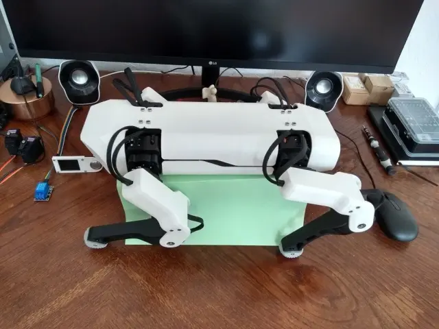
$130377 stars on GitHub · michaelkubina/SpotMicroESP32 SpotMicroESP32 is Michael Kubina's redesign of the SpotMicro quadruped, derived from KDY0523's original Thingiverse design, optimized for support-free 3D-printing and built around an ESP32-DevKitC. 12-DOF (3 servos per leg). Source: https://github.com/michaelkubina/SpotMicroESP32 SpotMicro family — pick your compute target: | Variant | Controller | ROS | |---------|-----------|-----| | SpotMicro (Pi) — mike4192 | Raspberry Pi | ROS Kinetic | | SpotMicro Jetson Nano | Jetson Nano | ROS Melodic | | SpotMicro ESP32 (this) | ESP32-DevKitC | No ROS | Hardware: 12 servos (3 per leg: shoulder yaw, upper, lower) ESP32-DevKitC main controller Optional ESP32-CAM for vision LiPo battery with custom mounting brackets Software ecosystem (community forks): Maarten Weyn BLE/IK firmware: https://github.com/maartenweyn/SpotMicroESP32 Blacksheep Nitro Fork (PCB + walking gait + RC): https://github.com/Blacksheep909/SpotMicroESP32-Nitro-Fork SpotMicro-Leika (FreeRTOS + 2 gaits): https://github.com/runeharlyk/SpotMicroESP32-Leika SpotMicroAI Community: https://spotmicroai.readthedocs.io/ Resources: Thingiverse: https://www.thingiverse.com/thing:4559827 Original SpotMicro by KDY0523: https://www.thingiverse.com/thing:3445283 Printing SpotMicro is a 12-DOF quadruped — 4 legs, 3 servos each — so the shoulder and limb parts must be printed once per leg (×4), and the chassis side is printed as a left/right pair (×2). This is the support-free Kubina redesign, so no supports are needed. Print quantities: ChassisSide ×2; FrontCover ×1, RearCover ×1, Cameramount ×1. Per leg (×4 each): BottomShoulder, InnerShoulder, OuterShoulder, LimbBallBearingMount, LimbBottomShell, LimbTopShell, LimbServohornMount, FootTip. Note on RearCover: the file is labelled a "Template." It is a customizable base cover meant to be edited (e.g. to add a cutout for your specific electronics/port layout) before printing, rather than a fixed final part — print it as-is if you don't need a custom opening. The upstream source also includes many experimental and alternate variants (different power-board mounting plates, optimized covers, mold parts); those are optional alternates and are intentionally excluded from this set, which is one clean buildable SpotMicro.
 Arm Robots
EvoArm
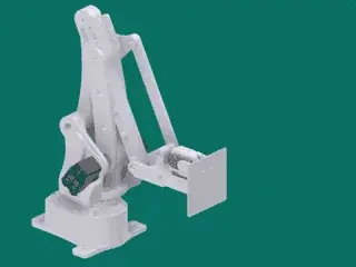
$380159 stars on GitHub. EvoArm is an open-source 3D-printable desktop robotic arm by Ali Shug, based in part on Armatec's LiteArm i2 (Thingiverse 480446). 3+2 DOF: three Dynamixel AX-12/AX-18A smart servos drive the main arm linkage, and two XL-320 servos drive a 2-DOF wrist effector. Source: https://github.com/AliShug/EvoArm Hardware: 3 main DOF: Dynamixel AX-18A (recommended) or AX-12 smart servos 2 wrist DOF: Dynamixel XL-320 servos Arduino Mega 2560 controller (multiple hardware UARTs) 74LS241 tri-state buffer for multiplexing servo data lines Optional Arduino Uno setup using software-serial trick Software: Python + PyGame inverse kinematics application (PyIK) 3D target position + end-effector orientation control Linear interpolation, bounds checking, reach-volume visualization UDP command interface for external control programs License: CC-BY-SA 3.0. Printing The print set is the complete 32-part EvoArm design from AliShug/EvoArm (). All parts are single-print (x1) unless noted; the arm uses several left/right mirror pairs — both halves are required, they are not interchangeable alternates. Mirror pairs (print both — L and R): / / / / Main linkage: , , , , , , , , , , . Base: , , . Effector / wrist: , , , , , . Bearings & spacers (print as many as the build needs): , , , — these are small support parts used at multiple 608-bearing joints; print extras as required. Cleanup note: the imported list previously held 32 entries but only ~20 unique parts — 12 parts were duplicated under opaque names while 12 other upstream parts (base, effector, hinges, forearm v2) were missing entirely. The duplicates were removed (verified by byte-size match) and the 12 missing parts re-added from upstream, giving a clean, complete, human-readable 32-part set that matches the canonical EvoArm design. Servos (3x Dynamixel AX-18A + 2x XL-320), the Arduino, and electronics are sourced from the BOM, not printed.
 Humanoid
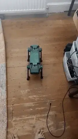
Zowi Biped
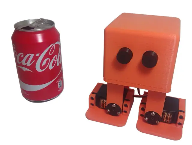
$70163 stars on GitHub · CC-BY-SA 4.0 · bq / JavierIH Zowi is the official open-source biped from bq (sponsored until 2016) — a compact 4-servo educational walking robot, descended from the Otto/BoB Thingiverse lineage (original concept by k120189, Thingiverse 43708). Designed entirely in FreeCAD so every part is editable and remixable. Licensed CC-BY-SA 4.0. Source: https://github.com/JavierIH/zowi Hardware: 4 Futaba S3003 (or compatible) servos BQ ZUM BT328 or Arduino-compatible board 4xAAA battery holder The repository ships the canonical body/chassis/leg/foot STLs plus a deep mods folder with remix variants: Forge, IronZowi, JIM, Kobuki, MicroRaider, Scopum, Zowarrior, Zowimanoid, Zowiquilator. Also includes Arduino code, schematics, and Spanish-language docs. Resources: Original Thingiverse concept: http://www.thingiverse.com/thing:43708 DIWO blog (Spanish): http://diwo.bq.com/zowi-introduccion-a-los-robots-bipedos/ License: CC-BY-SA 4.0. Printing Zowi is a 4-servo biped (Otto-family). The complete printed set is just five parts: body, chassis, leg, footL, and footR. Print one of each. footL and footR are a mirror pair (left and right feet) and are both required — they are not alternates. The LED-matrix mouth and ultrasonic/sensor modules are off-the-shelf electronics and are not printed. This Print All list was cleaned up to contain only the canonical Zowi parts. The upstream source repository also hosts several community remixes/mods (e.g. Forge, IronZowi, JIM) with their own arms, hands, heads, shields, and full-body redesigns; those are separate alternate builds, not part of the stock 4-servo Zowi, and have been removed along with a set of duplicate re-imported core files so the list yields exactly one buildable robot.
 Mobile Robots
Yertle Quadruped
$350Yertle — A 3D Printed Quadrupedal Robot for Locomotion Research Yertle is a 12-DOF quadruped robot designed for locomotion research. It fuses the leg geometry of the Kangal quadruped with the body geometry of SpotMicro, making most parts cross-compatible with the SpotMicro ecosystem. Creator: Jerome Alexander Graves · License: MIT · Status: Work-in-progress (functional; ROS2 integration pending) This Program is a learning entry point. The original firmware is C++ on an ESP32 with a Python GUI master controller — the orobot Program here exposes a stubbed JavaScript interface so you can explore the gait/command surface in-browser. To run on real hardware, follow the upstream build and flash instructions. Mechanical 4 legs × 3 DOF (hip yaw + hip pitch + knee) = 12 servos total Leg extension: ~20 cm Mass: ~1.8 kg Frame: PLA or ABS, printable on a 150 × 150 mm bed (Ender 3 Pro tested) Print time: ~2 weeks (5–10 h/day on a single Ender 3 Pro) 3D-Printed Parts This is the complete set of 21 unique parts: the four-piece outer Shell (Top, Bottom, Front, Back), the Frame (shoulder frames, servo mounts, body beams, electronics plate), and the Legs. Yertle is a 4-legged, 12-servo (3-DOF-per-leg) quadruped, so the leg and shoulder parts must be printed in multiples. Recommended material: PLA or ABS; a build plate of at least 150mm is needed for the larger parts. Print quantities (per the upstream build guide): Shell — Top Shell ×1, Bottom Shell ×1, Front Shell ×1, Back Shell ×1 (print these in a second color if you want a two-tone body). Frame — Inner Shoulder Frame ×2, Outer Shoulder Frame ×2, Upper Shoulder Frame ×2, Lower Shoulder Frame ×2, Left Servo Mount ×2, Right Servo Mount ×2, Servo Mount Top Bracket ×4, Side Body Beam ×2, Electronics Mounting Plate ×1. Legs (one set per leg, ×4 legs) — Femur ×4, Femur Servo Connector ×4, Inner Tibia ×4, Outer Tibia ×4, Short Link ×4, Long Link ×4, Left Shoulder ×2, Right Shoulder ×2. Software Architecture Master/slave over serial or UDP/WiFi: Slave (ESP32, C++/Arduino): servo control, sensor read, inverse kinematics, safety limits. Master (Python 3 GUI): gait generation, sensor fusion, ROS2 (todo). Runs on anything with WiFi + screen + Python 3. Simulation: Python-based built-in simulator; URDF available for Gazebo/Unity. Build Cost ~$315–350 total (servos dominate at ~$200). See full BOM in the upstream Design/README. Hardware Compatibility (BYOD) Yertle is not an orobot-firmware-native build. It uses a custom ESP32 firmware. Running the orobot Program against real hardware requires bridging the orobot WebSocket protocol to Yertle's UDP master/slave protocol — a custom integration tracked under the orobot ESP32 BYOD effort. Inspirations Kangal (leg design) SpotMicro (body geometry, parts compatibility) Open Quadruped Links GitHub Repository STL Files Design/README & BOM ESP32 Firmware Python Master GUI URDF / Simulation --- Extracted from commit on 2026-04-27.
 Mobile Robots
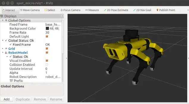
Spot Micro Quadruped
$450Spot Micro is a 4-legged open-source quadruped robot inspired by Boston Dynamics' Spot. Created by mike4192 in 2020, the project implements full motion control on a 3D-printed Spot Micro frame, including sit, stand, body angle, and walking gaits. Supporting libraries provide additional capabilities such as SLAM mapping using a body-mounted RPLidar. The robot uses a Raspberry Pi 3B running Ubuntu 16.04 with ROS Kinetic. Twelve PDI-HV5523MG servos (3 per leg) drive the legs through a PCA9685 i2c servo control board. The default 8-phase gait incorporates body movement to maintain balance and stability; an alternate trot gait achieves faster walking speeds. The 3D-printed frame originates from KDY0523's Thingiverse "Spot Micro" design (thing:3445283). This repository contributes the ROS-based motion control software, kinematics implementation, custom shoulder mounts, lidar mount, and SLAM integration on top of that frame. Hardware | Component | Notes | |---|---| | Computer | Raspberry Pi 3B | | Servo controller | PCA9685 (i2c) | | Servos | 12 x PDI-HV5523MG (or HV5523MG / cls6336hv) | | LCD panel | 16x2 i2c (optional) | | Battery | 2s 4000 mAh LiPo | | UBEC | HKU5 5V/5A regulator | | Lidar | RPLidar A1 (for SLAM) | | Frame | KDY0523 Spot Micro on Thingiverse | Estimated cost: $300-450 USD. Build time: 2-4 weeks. Skill level: Intermediate to Advanced (requires familiarity with ROS, Linux, and 3D printing). Software architecture The project is structured as a ROS Catkin workspace. Key nodes: spotmicromotioncmd — main C++ motion control node implementing kinematics, gaits, and state machine ros-i2cpwmboard — PCA9685 servo driver, controlled via i2c spotmicrokeyboardcommand — Python keyboard teleop spotmicrojoy — joystick teleop servomovekeyboard — manual servo calibration utility spotmicrorviz / spotmicroplot — visualization lcdmonitor — LCD status display Firmware status This program is BYOD (bring-your-own-device). The motion control runs on a Raspberry Pi with ROS, not on the orobot platform's native firmware. The orobot.io program here serves as a learning entry point and command interface; full hardware control requires checking out the GitHub repository, building the catkin workspace, and flashing the configured Pi image. See the project README for setup instructions. Attribution Source: https://github.com/mike4192/spotMicro Author: mike4192 License: MIT Frame design: KDY0523 (Thingiverse thing:3445283, separate license) Printing The print set is the 13 canonical SpotMicro parts from the upstream mike4192/spotMicro set. Because this is a 12-DOF quadruped (four identical-per-side legs), note the print quantities below — the static list shows each file once. Body (print x1 each): — central body shell — front body section — rear body section — base/floor plate Left legs (print x2 each — 2 left legs): , , , Right legs (print x2 each — 2 right legs): , , , Left and right leg parts are true mirrors, not interchangeable — print two of each side for the four legs (3 servos per leg = 12 DOF). One MG-class servo (PDI-HV5523MG) goes in each joint. Optional: — RPLidar A1 mount, only needed if you add the body-mounted lidar for SLAM. Skip it for a walk-only build. Cleanup note: the imported list previously held 39 files — the 13 real parts plus 26 duplicate re-imports** that all carried opaque names (each of the 13 parts was triplicated). The duplicates were verified by byte-size match against the upstream STLs and removed, leaving the clean, human-readable 13-part set. The 3D-printed frame derives from KDY0523's Thingiverse design (thing:3445283); servos, Pi, PCA9685, lidar, and battery are sourced from the BOM, not printed.
 Mobile Robots
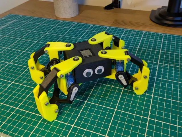
Kame32
$50Kame32 is an open-source quadruped walking robot by JavierIH. Built around an ESP32 and 8 servo motors, it walks, runs, dances, and performs a rich library of quadruped gaits — all controlled wirelessly via a built-in web-based gamepad over Wi-Fi. All structural parts are 3D-printable. A custom PCB (KiCAD gerbers included) centralizes servo wiring. Choose MG90S (higher torque) or SG90 servos — brackets for both variants are included. Specifications | Property | Value | |----------|-------| | Motors | 8 servos (MG90S or SG90) | | DOF | 8 (2 per leg) | | Controller | ESP32 Dev Kit | | Control | Web gamepad via Wi-Fi | | PCB | Custom KiCAD design (gerbers included) | | CAD | FreeCAD source file | | Build time | 1–2 weekends | | Skill level | Intermediate | Gaits Walk · Backward · Run · Omni Walk · Turn Left · Turn Right · Moonwalk · Dance · Up/Down · Push Up · Hello · Jump · Home All gaits use the Octosnake oscillator library — sinusoidal servo control with per-axis phase offsets. Hardware ESP32 drives 8 PWM servos at 50 Hz / 16-bit resolution. Per-servo calibration offsets stored in ESP32 NVS. Firmware PlatformIO / Arduino. Build environments: calibration (tune offsets) and gamepad (web UI controller). Attribution Creator: JavierIH Source: github.com/JavierIH/Kame32 License: CC BY-SA 4.0 (hardware) - GPL-3.0 (code) Build Guide Source repository with CAD, firmware, and assembly files: github.com/JavierIH/Kame32 Printing Kame32 is an 8-servo quadruped — 2 servos per leg, 4 legs. The servo brackets and legs come in two versions matched to the servo you use: SG90 (plastic-gear) or MG90S (metal-gear). This Print All set uses the SG90 version, which is the default servo in the bill of materials; MG90S is listed there only as an optional higher-torque upgrade. The four MG90S-specific files have been removed so the list yields one buildable robot rather than two overlapping servo sets. Print quantities: print body-box and body-cover once each (the chassis). The leg and bracket parts are per-leg, so the left/right SG90 leg and bracket files are each printed in multiples to cover all four legs (the robot has 4 legs, each with a left and right side); print the shared leg-link, bushing, and foot parts in matching multiples. Build one full set of leg hardware per leg from the mirrored left/right SG90 parts. Note: if you are building with MG90S metal-gear servos instead, use the corresponding -mg90s bracket and leg files from the upstream source (github.com/JavierIH/Kame32) in place of the -sg90 parts.
 Mobile Robots
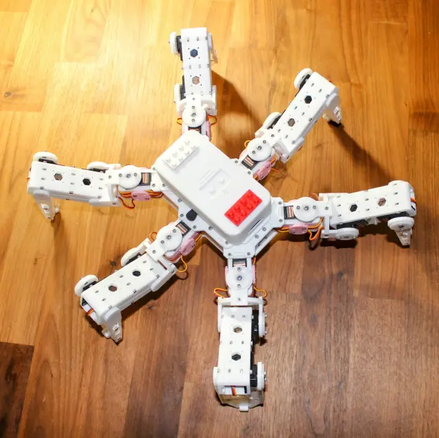
Hexapod
$120Hexapod — 3D Printed Six-Legged Walking Robot A fully 3D-printed hexapod robot with 18 servo motors (three per leg) providing lifelike, agile locomotion. Designed by rookidroid.com, this project uses either an ESP32 or Raspberry Pi Pico W/2W controller board with built-in WiFi for wireless remote control. The firmware supports over-the-air (OTA) updates so you can iterate on motion patterns without touching the hardware. Hexapod v2 is the recommended build. The original v1 used MG90S servos which are prone to failure; v2 upgrades to stronger 21G DS Power/Miuzei servos and is significantly more reliable. Do not use MG90S. Note: The controller board is proprietary to rookidroid.com. A generic ESP32 dev board can substitute — check the firmware docs for pin mapping. Specifications | Property | Value | |----------|-------| | Legs | 6 | | Servos | 18 x 21G (3 per leg: hip, knee, ankle) | | Controller | ESP32 or Raspberry Pi Pico W/2W | | Communication | WiFi (UDP port 1234) + OTA updates | | Power | 2 x 18650 Li-ion cells | | Printed Parts | 20 STLs, all print without supports | | Print time | ~40–60 hours total | | Skill level | Intermediate | Motion Modes The ESP32 firmware implements a pre-computed look-up-table gait system with 18 motion modes including: directional walking at 0, 45, 90, 135 degrees (left and right variants), 180 degrees; fast forward and backward; turn left and right; climb forward and backward; body rotations on X, Y, Z axes; and a twist mode. Attribution Creator: rookidroid.com Source: https://github.com/rookidroid/hexapod License: GNU GPL v3 Printing This is a complete, modular set of 20 unique parts. Because the hexapod has 6 identical legs (each with 3 joints), many parts must be printed in multiples. Per the upstream build guide, print the following quantities: Body (print once each): bodybase ×1, bodytop ×1, bodytopcover ×1, bodybattery ×1. Body (print in pairs): bodyside ×2, bodyfrontback ×2. Servo brackets (one per leg): bodyservoside1 ×6, bodyservoside2 ×6, bodyservotop ×6. Legs and joints (per-leg multiples): jointbottom ×12, jointtop ×12, jointcross ×6, legbottom ×6, legtop ×6, legside ×12. Feet (one set per leg): footbottom ×6, foottop ×6, footground ×6, foottip ×6. Optional: accessorycableholder ×1 (a cable-management add-on, not required for the robot to function). No supports are needed — orient each part as shown in the upstream print thumbnails. All 20 files are the correct, current parts; there are no duplicates, alternates, or version variants to choose between.
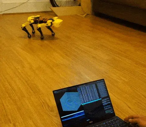 Mobile Robots
Spot Micro Quadruped — Jetson Nano (ROS Melodic)
$480Spot Micro Quadruped — Jetson Nano / ROS Melodic Port > Jetson-Nano-specific port of the SpotMicro design family. See also: SpotMicro (Pi) and SpotMicro ESP32 entries on orobot for other compute targets. A 12-servo, 4-legged 3D-printed open-source quadruped running ROS Melodic on an NVIDIA Jetson Nano. This fork () ports the original Raspberry Pi 3B + ROS Kinetic stack onto the Jetson Nano with ROS Melodic, unlocking the GPU for on-board SLAM, perception, and future learned-policy work. The robot supports sit, stand, body angle, and walk control via two configurable gaits (8-phase stable gait by default; faster trot gait optional). Body-mounted RPLidar A1 enables real-time SLAM and 2D mapping. State is published over tf2 with open-loop calculated odometry. Printing This is a 12-DOF quadruped with four legs, but the STL list holds only one left-leg set and one right-leg set. To build the whole robot you must print the leg parts in the quantities below (the body parts are single). Body — print x1 each: , , (3-piece shell) (base plate) Left legs — print x2 each (2 left legs): , , , Right legs — print x2 each (2 right legs): , , , That is 4 complete legs (one STS/MG-class servo per joint, 3 per leg = 12 DOF). Left and right parts are true mirrors, not interchangeable. Optional repo extras (lidar mount, chassis reinforcements) and the status LCD are not part of this print set. Hardware Compute: NVIDIA Jetson Nano (this port). Original target was Raspberry Pi 3B. Frame: Thingiverse Spot Micro (KDY0523) — thing:3445283 Servos: 12× PDI-HV5523MG (or cls6336hv — print files compatible) Servo control: PCA9685, i2c Power: 2S 4000 mAh LiPo direct to servo board; HKU5 5V/5A UBEC for Jetson + peripherals Sensing: RPLidar A1 (body-mounted) Optional: 16×2 i2c LCD panel for state readout Software stack OS: Ubuntu 18.04 (for ROS Melodic on Jetson Nano). Original used Ubuntu 16.04 + ROS Kinetic. Framework: ROS Melodic catkin workspace Languages: C++ (motion control, kinematics) + Python (keyboard command, plot) Key packages: , , (URDF), , , Build flow 1. Flash Jetson Nano with Ubuntu 18.04 + ROS Melodic. Add a 1 GB SWAP partition (catkin will OOM without it). 2. Create a catkin workspace, clone this repo into , run . 3. . 4. . 5. Calibrate all 12 servos using the spreadsheet + workflow before powering the legs. 6. on the Jetson; from a remote machine. Family cross-reference This is one of three SpotMicro variants on orobot — pick the compute target that matches your build: SpotMicro (Raspberry Pi) — original , Pi 3B + ROS Kinetic. SpotMicro ESP32 — , microcontroller-only port without ROS. SpotMicro Jetson Nano (this entry) — Jetson Nano + ROS Melodic, GPU-accelerated SLAM. Source Repo: https://github.com/0x49b/spotMicro-ROS-Melodic-Jetson-Nano Commit: 8c027c8a357dceace856d586022954205bc247ed License: MIT Upstream: (this is a Jetson Nano fork)
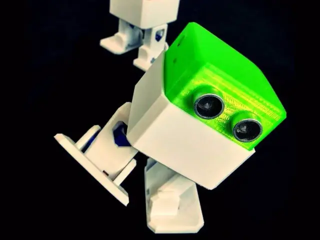 Mobile
Otto DIY
$64Otto DIY — Bipedal Walker Robot Otto is one of the most beloved open-source DIY robots: a small bipedal walker that anyone can build with a 3D printer, an Arduino Nano, and four micro servos. Originally created by the Otto DIY community, Otto can walk, turn, dance, sing, and emote with optional ultrasonic, sound, and LED matrix add-ons. This Program is a learning interface for the Otto DIY platform. Full hardware control runs on the Arduino firmware in the source repo below. The orobot.io control sandbox lets you experiment with the command surface before wiring it into your own Otto. Specs | Property | Value | |----------|-------| | Type | Bipedal walker | | Servos | 4 × SG90 micro servo (LeftLeg, RightLeg, LeftFoot, RightFoot) | | Controller | Arduino Nano (also Uno, Micro, Mega, ESP8266, ESP32 in dev) | | Height | ~12 cm | | Estimated cost | $50–75 (core build) / $80–110 (with sensors) | | Estimated build time | 2–6 hours | | Skill level | Beginner / Intermediate | Source Repo: https://github.com/OttoDIY/OttoDIYLib (canonical Arduino library, v13.0) STLs + assembly guide: https://www.ottodiy.com/ Library examples: https://github.com/OttoDIY/OttoDIYLib/tree/master/examples Otto Blockly / app: https://www.ottodiy.com/#app Author: Otto DIY community License: GPL v3 (code) + CC-BY-SA 4.0 (mechanical design) Hardware integration status Otto runs on Arduino Nano with the OttoDIYLib firmware. orobot-firmware does not yet have Arduino Nano support — this Program provides the learning interface and command surface. To run a real Otto, flash OttoDIYLib onto your Arduino directly and use the bundled examples (, ). Capabilities Walk, turn, jump, moonwalk dance, ~10 named gestures (Happy, Sad, Angry, Love, Confused, Wave, Magic, Fail, Sleeping…), and 19 built-in songs. Full API in the OttoDIYLib examples. Credits Massive thanks to @JavierIH, @Obijuan, @sfranzyshen, and the dozens of contributors who have built and maintained Otto DIY for nearly a decade. Otto is one of the projects that proved tiny, friendly, accessible robots could be a global open-hardware movement.
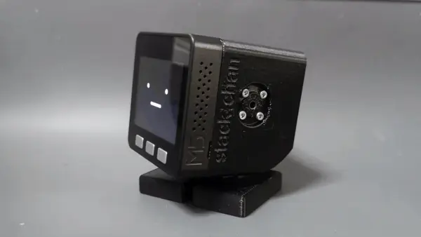 Humanoids
Stack-chan
$1301,382 stars on GitHub. Stack-chan — Palm-Sized Companion Robot Stack-chan is a palm-sized, open-source companion robot driven by an M5Stack microcontroller and JavaScript firmware. Created by Shinya Ishikawa, Stack-chan sits on your desk, turns its head to watch you, expresses emotions on its built-in display, and responds through speech. Source: https://github.com/stack-chan/stack-chan Capabilities Servo-driven head gaze/tracking Emotive faces (happy, angry, sad) + fully customizable face expressions Speech synthesis Composable behaviors ("mods") — mix and layer: expressions, tracking, speech, M5Unit addon support Programmable in JavaScript on the Moddable SDK (embedded JS framework; no C/Arduino required) Servo Paths — Pick Before You Print Two mutually exclusive configurations that change both the case geometry and electronics: | Path | Servos | Notes | |------|--------|-------| | PWM | SG90 / MG90S | Simpler, cheaper, standard hobby servo wiring | | Serial TTL | RS30X series | Smoother motion, requires a buffer IC and serial-servo case geometry | Picking a path determines which STL set and which PCB you build. Build Notes Requires a custom PCB — order Gerbers from JLCPCB/PCBWay ( directory in the repo) Modular 46-part printable enclosure (shell, bracket, feet, spacer, accessories: hat, backpack variants, Lego adapter) An official commercial M5Stack version (StackChan) is available; the open-source org fork is the reference for DIY Metadata GitHub stars: 1,382 Author: Shinya Ishikawa & community License: Apache 2.0 Links Firmware () STLs () Schematics + PCB () Roadmap Demo video (YouTube, EN subs)
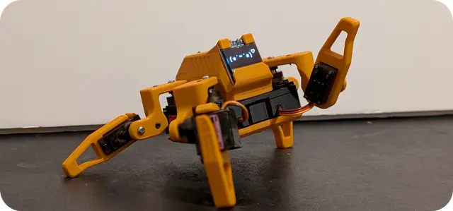 Mobile Robots
Sesame Quadruped
$851,619 stars on GitHub. Sesame is an affordable, open-source mini quadruped robot powered by an ESP32 microcontroller. Designed by Dorian Borian, Sesame uses 8 MG90S metal-gear servos (two per leg) for 8-DOF locomotion and features a 128×64 OLED display that serves as an expressive robot face. Source: https://github.com/dorianborian/sesame-robot All mechanical parts are fully 3D-printable on a standard FDM printer. The hardware folder contains both parametric STEP and Fusion 360 source models alongside the STL files, allowing full customization. The frame, internal structure, covers, and leg segments are all available as individual STLs. The ESP32 firmware handles inverse kinematics, face animations on the OLED display, and a WiFi-based control interface accessible from any browser. A desktop companion app (Sesame Studio) is included for easy gait configuration and pose tuning without writing code. Community documentation covers full assembly with detailed wiring diagrams and a comprehensive BOM. Hat variants are available (enclosed, open, cat ears) for personality customization. With over 1600 GitHub stars, Sesame has become a go-to beginner quadruped platform. License: Apache 2.0.
 Mobile Robots
Legolas Biped
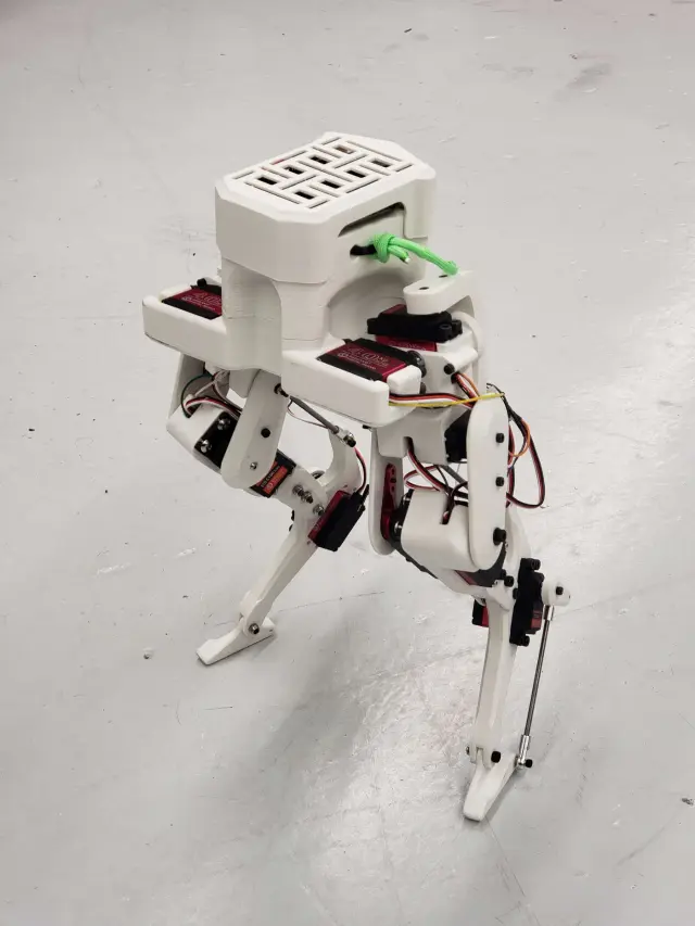
$30045 stars on GitHub. Legolas is an open-source mini bipedal robot designed by David Ho, a master's student at the University of Michigan. Inspired by the Cassie bipedal robot from Agility Robotics, Legolas reproduces the same inverted-leg "cassowary" geometry at a fraction of the cost using hobby servos and 3D-printed parts. Source: https://github.com/daviddoo02/Legolas-an-open-source-biped The robot stands roughly one foot tall and walks using 10 hobby servo motors: eight 40 kg-cm servos and two 80 kg-cm servos, coordinated through a PCA9685 16-channel PWM servo driver board. An MPU6050 inertial measurement unit provides balance feedback, and a Raspberry Pi 4 handles all control computation. The design deliberately omits an onboard battery — the robot runs tethered for continuous testing without power interruptions. All structural components are 3D-printable in standard PLA/PETG with roughly 1 kg of filament. The 20-part printable set covers the complete lower body: foot, shoe variants (A/B), shin, thigh (inner and outer), foreleg (A/B/C), hip joints (1A/1B, 2, pitch A/B), main body, body cover, wire connector container, ADC mount, servo cover, and a test bench adaptor for development work. CAD source files are provided in SolidWorks format. A MuJoCo simulation model is included for reinforcement learning experiments before deploying to hardware. License: MIT.
 Mobile Robots
Sawppy Rover
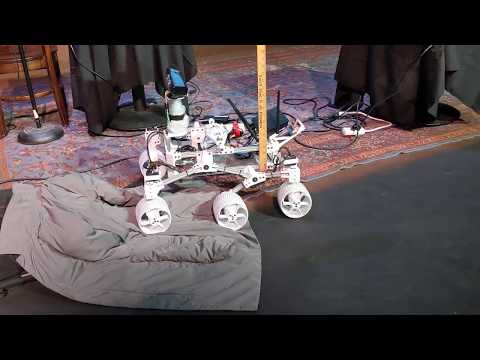
$320491 stars on GitHub. Sawppy the Rover is a 3D-printed, motorized model of NASA's Mars rovers Curiosity and Perseverance, buildable for under $500 in parts. Created by Roger Randolph as a more accessible alternative to the JPL Open Source Rover, Sawppy replicates the iconic rocker-bogie suspension system that allows rovers to traverse rocky terrain with all six wheels remaining in contact with the ground. Source: https://github.com/Roger-random/SawppyRover The suspension uses the same kinematics as the real Mars rovers — a passive differential mechanism connects the rocker-bogie suspension arms so the rover body stays level even when wheels traverse obstacles at different heights. All structural parts are fully 3D-printable on a standard FDM printer; the STL directory contains 30 tested parts (this Print All set keeps the 23 canonical LX-16A parts plus an optional 2-part display housing — see Printing below). Drive hardware uses LX-16A serial bus servos (10 total: 6 wheel drive, 4 steering), which are significantly cheaper than the equivalent Dynamixel servos while offering position feedback. The control stack runs on a Raspberry Pi and supports Arduino wired control, R/C control, ROS Kinetic, ROS Melodic, and ROS2 Humble — including full Gazebo simulation support. An active builder community exists on Hackaday.io with numerous documented builds. A "Micro Sawppy" variant targeting $100 and elementary-school builders is also available. Live Onshape CAD allows full modification. License: MIT. --- Install Notes Sawppy's software stack varies by hardware variant — the original uses LewanSoul LX-16A serial bus servos; newer variants use different controllers. Software lives in separate platform-specific repos (search for "Sawppy ROS" or "Sawppy ESP32"). The orobot Program code is a reference stub. Start from the Sawppy docs directory which links the correct sub-project for your build. Printing Six-wheel rocker-bogie rover. The 23 canonical structural STLs below are from the upstream directory and match the BOM's LewanSoul LX-16A serial-bus servos (6 drive + 4 steering = 10 total). Print quantities are per rover, not one-each: Wheels & steering (the big multiples): Wheel — print 6× (all six wheels) Wheel-Hub — print 6× Bogie-Wheels — print 6× (wheel mounts) Steering-Knuckle — print 4× (the four corner/steering wheels) Fixed-Knuckle — print 2× (the two middle, non-steering wheels) LX-16A---Coupler — print 6× (one per drive servo) LX-16A---Bracket — print ~10× (servo brackets; one per LX-16A) Corners & suspension (print 1× unless noted): Front-Corner ×2, Rear-Corner ×2, Body-Corner ×4 (rocker-bogie corner brackets) Rocker ×2, Rocker-Body-Mount ×2, Bogie-Body ×2 (left + right suspension arms) DiffBrace, DiffEnd, DiffLink, DiffLower, DiffUpper — the passive differential (×1 each unless your build doc says otherwise) Rod-Support — for the 8 mm shafts (print as needed) Clip2n125, Clip3n20 — small retaining clips (print several of each) Chassis / electronics (1× each): Battery-Tray, Power-Panel Optional add-on (kept, ≤3 optional): DisplayBottom + DisplayTop — a small status-display housing (community add-on). Skip if you are not fitting a display. Removed alternates (not needed for the LX-16A build): the upstream community modification set under was trimmed out — , (these are for Dynamixel AX-12 servos, not the LX-16A in the BOM), and , , (a 25 mm-motor variant). If you are building the AX-12 / 25D variant instead, print those from the upstream repo's folder in place of the LX-16A brackets/knuckles. Use ~3× 608 bearings per build along with M3 heat-set inserts. PLA on a standard FDM printer is fine.
 Mobile Robots
ArachnoBot Hexapod
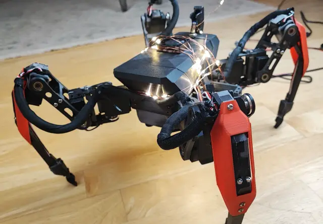
$17568 stars on GitHub. ArachnoBot is a 3D-printed hexapod spider robot with 18 degrees of freedom — three joints per leg across six legs. Built around a central frame with six symmetrical legs, it uses standard hobby servos for all joints. The project provides complete STL files for every structural component: the frame, central servo holders, side servo holders, coxa links, femur links, tibia tips, claws, electronics plate, controller plate, power compartment, and carapace. Source: https://github.com/robs-tech-workbench/hexapodspiderbotmodel The design is modular — a carapace plate covers the body electronics, the power compartment provides protected battery mounting, and a push-fit stand allows the robot to rest in a stable neutral position. Assembly documentation and BOM are provided in the README. The design is inspired by the MakeYourPet community hexapod designs by Discord user "amelendez8", who contributed the leg geometry that enables smooth multi-gait locomotion. The original inspiration comes from the MakeYourPet project, adapted and extended for this build. At 25 unique printable parts covering every leg segment and body panel, this is a complete hexapod kit that teaches hexapod kinematics, servo coordination, and 6-legged gait planning. License: MIT. --- Install Notes This repository is primarily mechanical CAD files (FreeCAD, STL) with minimal software. Servo control code, if any, lives in a separate or forked repository. The orobot Program code is a reference stub only. To run this robot, find the corresponding firmware repo and adapt the serial bridge code in this Program's editor to match the actual command protocol.
 Arm Robots
SaturnArm
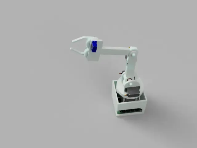
$186SaturnArm — A Simple 5-DOF Robotic Arm A budget-friendly 3D-printed robotic arm with inverse kinematics, controlled by a Raspberry Pi Zero 2 W. Originally built as a VR-teleoperation experiment inspired by NASA Mars rover footage, SaturnArm gives you a fully assembled desktop arm for ~$200 USD in parts. Highlights 5 actuators total: 3× MG996R servos, 1× NEMA23 stepper (TMC2208 driver), 1× SG90 mini-servo (claw) On-board PCB (KiCad sources included) consolidates power + signal C++ firmware on Raspberry Pi Zero 2 W with simple text-command protocol (, , ) Optional Pi Camera Module B+ for vision feedback 24V → 6V step-down for servos; LM2596 for logic What you'll build 3D-print the chassis (single-plate G-code provided for Bambu Lab A1m, ~$31 of filament), order the BOM from AliExpress, assemble the PCB at JLCPCB ($3.50 for 5 boards), wire it up, flash the firmware, and calibrate. --- Source: github.com/regular030/SaturnArm · Creator: regular030 · License: unspecified (treat as ARR — credit the creator, link the repo) If you're the maker and you spot your work here: come claim it. Sign up, take the title, run the crew. Printing A clean, complete 7-part set for one SaturnArm — every part maps directly to the pictured arm, all print-one-each, no duplicates/variants/sim meshes. PLA (~485 cm³, ~$31 filament); single-plate G-code for a Bambu A1m is provided upstream. Print one each (7), bottom-to-top: PCBChassis — the electronics box that houses the PCB at the base Standoff-Bot — PCB standoffs/mounts inside the chassis ArmBase — rotating base (driven by the NEMA23 stepper) Arm1 — lower arm link arm2 — upper arm link TopClawL + TopClawR — the two halves of the parallel-jaw gripper/claw (both required — they are the left and right jaw, not alternates) Actuators (not printed): 3× MG996R servos (main joints) + 1× NEMA23 stepper with TMC2208 (base rotation) + 1× SG90 mini-servo (claw), on a Raspberry Pi Zero 2 W with the project's custom PCB. No changes were needed to this list — it was already correct. (File names use mixed casing, e.g. arm2 vs Arm1; cosmetic only, doesn't affect printing.)
 Grippers
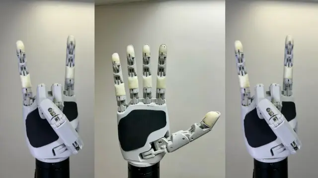
Aero Hand Open
$314Aero Hand Open is an open-source, tendon-driven robotic hand designed by TetherIA for dexterous manipulation research. Unlike expensive proprietary solutions, this hand focuses on simplicity, reliability, and accessibility — fully 3D-printed structure with off-the-shelf electronic components. Key Specs: 7 DoF | 16 joints | 5 fingers | 389g | ESP32-S3 controller | 7× Feetech HLS3606M servos Attribution: TetherIA Inc. — https://github.com/TetherIA/aero-hand-open License: Design files (CAD/STL/BOM/docs) — CC BY-NC-SA 4.0 | Software (firmware/SDK) — Apache-2.0 Source: https://github.com/TetherIA/aero-hand-open Docs: https://docs.tetheria.ai | Shop: https://shop.tetheria.ai Printing This is a single left hand (all parts are prefixed; the upstream repo also publishes a mirrored right hand under prefixes if you need the opposite hand). Structural / palm (1 each): leftbaselink — palm/chassis lefttlink — thumb carpometacarpal mount Five finger chains. Each of the four fingers (index, middle, ring, pinky) is a four-link chain; the thumb is its own four-link chain: Index: leftindexproximal / middle / distal / tip Middle: leftmiddleproximal / middle / distal / tip Ring: leftringproximal / middle / distal / tip Pinky: leftpinkyproximal / middle / distal / tip Thumb: leftthumbmcp / proximal / distal / tip Mount adapters (pick the one that matches your wrist/base — optional): 135degreesadapter — for a 135° angled mount threadedmountadapter — for a threaded base mount Print in PLA, 0.2 mm layer height, tree supports on the build plate only. Per the BOM, several small hardware items are not separate STLs: the 6× cable spools and the silicone finger pads are produced by other means (spools are integral / cast pads use Ecoflex 00-30 in a mold). Buy undersized 2x10 pins — standard 2x10 pins are too tight for the 2x5x2.5 mm bearings and cause joint stiffness. Route the tendons before final assembly of each finger module; retrofitting cables through assembled joints is extremely difficult. The full set is 24 STL files (22 hand parts + 2 optional mount adapters), driven by 7× Feetech HLS3606M servos.
 Drawing Robots
BrachioGraph Pen Plotter
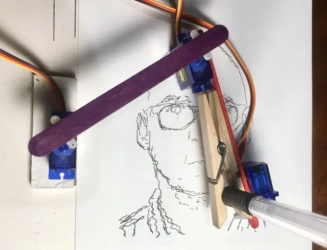
$40BrachioGraph — the cheapest robot that makes art Two sticks, three tiny servos, a clothes peg, and a Raspberry Pi. That's the whole robot. The BrachioGraph is a 2-DOF planar arm that holds a pen and draws — your name, a portrait of Immanuel Kant, whatever vector paths you feed it. It is quite possibly the cheapest useful robot you can build (~€14 in parts if you already own a Pi), and the only one in this catalog whose output you can stick on the fridge. Created by Daniele Procida · evildmp/BrachioGraph · MIT License · Official tutorial: brachiograph.art Featured by the Raspberry Pi Foundation and Hackaday. --- How it works The arm is two 8cm links: a shoulder servo swings the inner arm, an elbow servo swings the outer arm, and a third servo nudges the pen up and down via a clothes peg. Closed-form inverse kinematics (two lines of / — no solver, no calculus degree required) converts an (x, y) target in centimetres into two joint angles. Chain enough targets together and you have a drawing. The default plotting area is roughly 14 × 9 cm — postcard-sized art. This program ships the IK adapted directly from the upstream (MIT, © 2019 Daniele Procida) plus ready-made actions: park, pen up/down, draw the bounds box (the canonical calibration check), and a zigzag test stroke. Two ways to build the arms 1. No 3D printer — the canonical build. Popsicle sticks, hot glue, a clothes peg. This is how the original is designed and it works disarmingly well. Full instructions at brachiograph.art (build time: about an hour). 2. 3D-printed parts (community, by ringo2k): Printables model 926063 — 5 parts attached to this program: , , , , . Inner arm is 80mm center-to-center, matching the official geometry. Standard PLA, 0.2mm layers, 20% infill is plenty. No supports needed except possibly the Pi mount base. Wiring — two control paths orobot-native (what this program drives): put the three SG90s on a PCA9685 16-channel PWM board ($5–6) on the Pi's I2C bus — shoulder → channel 0, elbow → channel 1, pen lifter → channel 2. The orobot firmware's bridge drives them through a serialized command queue, and this program's actions work out of the box. Power the servos from the PCA9685's V+ terminal (5V), not the Pi's 3.3V rail. Upstream-standalone (the original way): servos wired directly to GPIO 14 (shoulder), GPIO 15 (elbow), GPIO 18 (pen), driven by the daemon at 50Hz with 500–2500µs pulses. This is the path the official tutorial documents, and the right choice if you want to run the full upstream Python stack (bitmap vectorization, calibration notebooks) without orobot. Note: wants exclusive GPIO PWM control — don't run both stacks against bare GPIO at once. Assembly overview (Condensed from the structure of the official tutorial — read it in full, it's excellent.) 1. Build the base. Glue the shoulder servo to a board or use the printed (holds the Pi too). 2. Build the arms. Inner arm: 8cm between servo centers — one servo body glued at each end (or print ). Outer arm: 8cm from elbow to pen (or print + glue the clothes peg at the 80mm mark). 3. Center the servos FIRST. Drive all three to their midpoint (1500µs) before pressing on the horns. A horn glued off-center eats half your drawing area. 4. Attach the pen lifter. The third servo lifts the outer arm a few millimetres (printed gives a better 90° lifting action than a bare horn). 5. Wire it. PCA9685 path: servo plugs onto channels 0/1/2, board to Pi I2C (SDA/SCL/5V/GND). Standalone path: signal wires to GPIO 14/15/18, 5V and ground rails on a mini breadboard. 6. Calibrate. Run Draw Bounds Box. If corners get skipped or the box is a parallelogram, your horns are off-center or arm lengths are off — adjust and repeat. (Upstream has a deeper calibration routine with per-servo pulse-width tuning for the dedicated.) 7. Draw. Pen down, send coordinates, make art. Sign your plots; the robot doesn't mind. What's honest to expect SG90s are $2 servos with the repeatability of a $2 servo: lines wobble, corners round off, and that is the charm — BrachioGraph drawings have a hand-drawn, slightly anxious quality that plotter people pay good money to fake. For converting actual images to plottable paths, the upstream repo's vectorizes bitmaps; a browser-side "paste an SVG, robot draws it" pipeline is the natural next step for this program but isn't built yet.
 Camera Bots
Pan-Tilt Camera Tracker
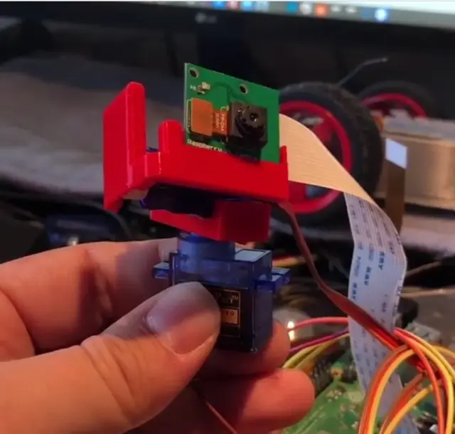
$60Two micro servos, one Pi camera, zero excuses. The Pan-Tilt Camera Tracker is the smallest robot that can look at you — a $60–100 camera head that pans, tilts, streams live video to your browser, and follows faces using nothing more exotic than OpenCV and a proportional control loop. It is orobot's first vision-class robot: where every other robot in the catalog moves, this one sees. What it does in your browser, today Live camera stream — with enabled in the program config, the orobot firmware pushes MJPEG frames from the Pi camera to the gateway, and the operator page's camera panel shows the live view (~10 fps push loop). Note: the firmware's frame capture currently shells out to , the legacy Pi camera stack — on Pi OS Bookworm, enable legacy camera support or symlink . Pan/tilt control — Center, Sweep Scan, and Look Left/Right/Up/Down actions drive the two servos through the firmware's PCA9685 servo bridge. The joint sliders work too. On-device detections — the "What Do You See?" action asks the firmware for an inference pass (); detections come back as bounding boxes in the operator Vision panel and as device log lines. Requires a vision backend on the Pi (ONNX Runtime via , or transformers.js). Closed-loop tracking steps — feed the action a detection's offset from frame center and the head nudges proportionally toward it. Chain steps as detections arrive and you have a face tracker. Honest limits: fully autonomous, continuous high-rate face tracking (detect → correct, many times per second) runs best as an on-device Python script (pattern below) rather than through round-trips to the cloud. And nobody — including the upstream tutorials — has published verified FPS numbers for Haar-cascade face detection on a Pi Zero 2 W. That's why we recommend a Pi 4 or Pi 5: quad-core with headroom, so detection at 640×480 stays fluid instead of slideshow. How the tracking works The algorithm is delightfully simple and fully public knowledge: 1. Grab a frame from the camera (640×480 is plenty). 2. Detect a face — OpenCV Haar cascade () or a DNN detector if you have the horsepower. 3. Compute the detection centroid's offset from the frame center, normalized to −1..1. 4. Multiply by a proportional gain (this program uses Kp = 0.55 with an 8% dead band) and the camera's field of view to get a servo correction in degrees. 5. Move pan/tilt by that correction. Repeat. The face stays centered; the robot appears to "watch" you. When no face is found, the head runs a slow pan sweep — the classic searching behavior. Two ways to build it Path A — no 3D printer (recommended first build): the Adafruit Mini Pan-Tilt Kit #1967 ($18.95) arrives assembled with both micro servos already installed. Add a Pi camera and a Pi and you're done with mechanics. Follow the Adafruit assembly guide if you buy the unassembled version. Path B — print the brackets: the two STLs attached to this program (pan adapter + tilt adapter) are "3D Printed Raspberry Pi Pan-Tilt Camera Brackets" by Makerhacks (CC BY 4.0). They take two standard SG90 servos (~$3/pair in multipacks) and a Pi Camera V2. Print in PLA or PETG at 0.2 mm layers, 20% infill — these are not structural parts. Assembly overview 1. Mechanics — assemble the pan-tilt head: pan servo in the base, tilt servo in the bracket, camera plate on the tilt arm (Adafruit guide for the kit; the printed brackets snap/screw around the SG90s the same way). 2. Center first! Power each servo and command it to its center (0°/1500 µs) before screwing the horns down. Skipping this is the #1 way to end up with a head that can look hard left but not right. 3. Camera — connect the Pi Camera V2 ribbon to the CSI port; route the ribbon with slack so a full tilt doesn't tug it. 4. Wiring (orobot-native) — servos to PCA9685 channels 0 (pan) and 1 (tilt); PCA9685 to the Pi's I2C pins; servo power from a 5 V supply with common ground. 5. Wiring (standalone alternative) — servo signals direct to GPIO BCM 17 (pan, pin 11) and BCM 23 (tilt, pin 16). This is the wiring the classic tutorials use (Pimoroni, DigiKey). Use it for the standalone Python tracker, not together with the orobot firmware's servo bridge — one driver per servo, please. 6. Software — flash Pi OS, install orobot firmware, enable the camera in this program's config. For standalone tracking write a Python 3 script with ≥ 4.x and (the venerable Python 2 + OpenCV 2 demos predate Bookworm and won't run unmodified). Attribution & design references 3D-printed brackets: Makerhacks on Printables, model 907524 — Creative Commons Attribution (CC BY). The two STLs attached here are redistributed under that license with attribution. Bracket photos: from the same Printables listing, CC BY, © Makerhacks. Tracking pattern references: Pimoroni's pan-tilt face tracker tutorial and DigiKey's Raspberry Pi pan/tilt face tracker build. The widely-known repository was consulted as a behavioral reference only: it carries no open-source license, so no code from it appears in this program. The control code here is a clean-room implementation of the publicly documented detect-centroid-correct pattern, written for orobot. Hardware kit: Adafruit Mini Pan-Tilt Kit #1967 (we are not affiliated; it's just good).
 Arm Robots
5-DOF IoT Robot Arm
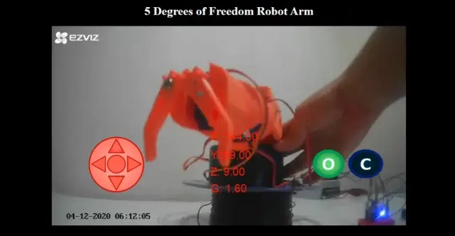
$70An open-source 5-degree-of-freedom robot arm you build, print, and control from a browser over WiFi — with a live IP-camera video feed of the arm as you drive it. The arm is 3D printed and actuated by 5 hobby servos (2x MG996R for the base/shoulder, 3x SG-90 for the elbow/wrist/gripper) driven by a PCA9685 16-channel PWM driver. An ESP8266-01s microcontroller joins your WiFi network and talks to a small NodeJS web server over Socket.IO, which streams commands out to the arm and relays a live RTSP camera feed back to the browser. The server computes inverse kinematics (Denavit–Hartenberg parameters) so you can jog the end effector in X/Y/Z instead of driving each joint by hand, and it rejects moves outside the arm's reachable workspace. Originally built as an educational robotics + web-programming project by Victor Cadillo Guzman. Attribution & License Creator: Victor Cadillo Guzman (vcadillog) Source: https://github.com/vcadillog/3D-printed-IoT-Robot-Arm-5DOF-NodeJS No explicit license file in the source repository — verify terms with the author before redistributing derivative hardware/software commercially. What you'll need A 3D printer, an ESP8266-01s (or compatible ESP8266 module with 2+ GPIO), a PCA9685 servo driver, 5 hobby servos, an IP camera, a 5V/5A power supply with a 5V→3.3V step-down converter, and a computer (a Raspberry Pi works) to run the NodeJS web server. Note on orobot platform support: this design's control stack (ESP8266 + PCA9685 + a standalone NodeJS/Socket.IO app) is not orobot-firmware-native — it runs its own server outside the orobot device pipeline. This Program is a learning/reference entry point; treat the code tab as illustrative of the orobot Program IDE model (motors/poses/sequences), not a 1:1 port of the original inverse-kinematics control loop. Build and run the original from source (see GitHub link) for the full IP-camera + IK experience.
 Delta Robots
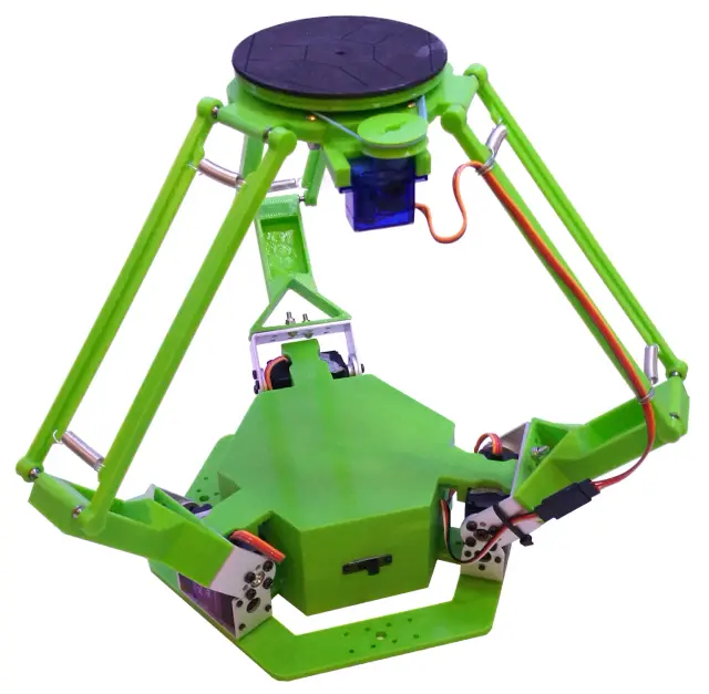
Delta Robot
$130A 3D-printed parallel delta robot — orobot's first entry in this class. Three servo-driven arms suspend a moving end-effector platform beneath a fixed base, giving fast, precise pick-and-place motion in a small, lightweight footprint. Designed and built by isaac879, who also designed the Pan-Tilt Camera Tracker already in this catalog. What it is Unlike a jointed arm, a delta robot keeps its motors fixed to the base and drives the end effector through three parallel linkages — the geometry that makes industrial delta robots so fast at repetitive pick-and-place work (sorting, packaging, light assembly). This build brings that same parallel-kinematics layout to a desktop, 3D-printed, servo-actuated scale. Specs Actuators: 3x HJ S3315D digital servos (arms) + 1x SG90 micro servo (gripper/end-effector rotation) Controller: Arduino Nano Comms: HC-05 Bluetooth module (serial link to a host PC — a Windows serial controller app is included in the source repo) at 57600 baud Power: 3S 11.1V LiPo through a buck converter to 6V for the servo rail Frame: 3D-printed PLA arms/base/effector + 333mm aluminium tubing legs (16mm OD / 14mm ID) Control: Cartesian jog (X/Y/Z) and absolute-position moves over a custom serial protocol; a stored move-sequence array supports simple programmed routines Build The mechanical design, wiring schematic, and 20 STL parts are hosted on the author's Thingiverse page. The Arduino Nano firmware ( / ) implements the inverse kinematics and serial command set; it depends on the author's companion Iibrary utility library. A Windows desktop controller (, MSVC/) is included for jogging the arm and building move sequences over the Bluetooth serial link. Hardware & license notes Firmware/code license: MIT (isaac879, 2019) — the GitHub repository's file. CAD/STL license: the 20 STL files are hosted separately on Thingiverse under CC BY-NC-SA 4.0 (Attribution-NonCommercial-ShareAlike) — a stricter, non-commercial license than the code. Anyone printing this design must follow that license's attribution and non-commercial terms; this is flagged for human review before this program is published. Controller: the project uses an Arduino Nano, which orobot's hardware registry does not yet have a dedicated entry for — this program is tagged with the closest existing BYOD entry (Arduino Uno) as a placeholder pending a proper Arduino Nano hardware type. This is a learning interface: the code in this Program is a simplified command-relay stub, not the real inverse-kinematics firmware. Full functionality requires flashing (plus the dependency) to a real Arduino Nano wired per the schematic below. Source Firmware/code: https://github.com/isaac879/Delta-Robot (MIT) STL files (CC BY-NC-SA 4.0): https://www.thingiverse.com/thing:3465651 Project video: https://youtu.be/vONuJPu1z3s
 Humanoids
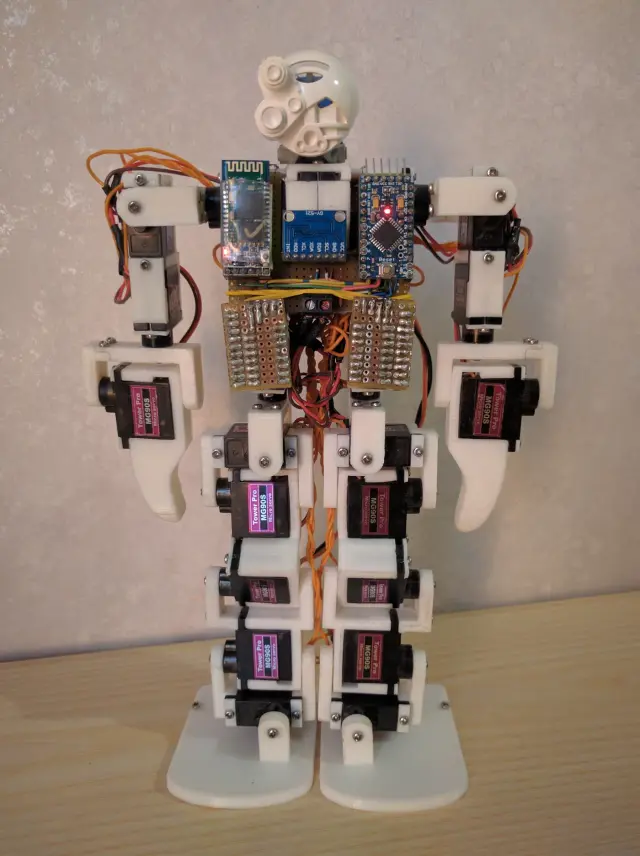
RoboPrime
$95RoboPrime is a full-featured 21-DOF, 3D-printed bipedal humanoid built around a $10-class Arduino Pro Micro (ATmega328p). Every joint is an MG90S 9g micro servo, driven through a pair of 74HC4017 Johnson decade counters that let a single microcontroller address up to 20 servos over one interrupt-driven serial-servo channel — a clever hack that avoids needing a dedicated servo driver board. An HC-05 Bluetooth module gives wireless serial control from a phone or PC, and an onboard MPU-6050 IMU is present in hardware for future balance work (unused in the shipped firmware). Two full physical builds (v1 and v2) exist with photos, plus a soldered custom carrier board, hand-wired point-to-point on protoboard. The firmware implements a small command language (S0-S3, Q0, C0) for single-servo moves, timed sweeps, queued/synchronized movement planning, and calibration, plus three working hardcoded animations: Hello (wave), Sit Down, and a cheeky third gesture. Walking gaits are stubbed in the animation table but marked work-in-progress by the original author. Built by Simone Primarosa (simonepri) and shown at Maker Faire Rome. Originally documented as a high-school capstone project (write-up in Italian, linked from the source README). This orobot.io program is a control-interface port — it re-expresses the original robot's home/hello/sit-down/stand-up choreography using orobot's motor/pose/sequence model so you can drive RoboPrime from the browser Operator panel. The original ATmega328p + HC-05 firmware is not orobot-firmware-compatible out of the box; see Required Hardware below. Full source (firmware, wiring, 3D models) is on GitHub. Source: https://github.com/simonepri/roboprime License: GPL-3.0 (project) / MIT (firmware files) Original author: Simone Primarosa — https://github.com/simonepri
 Camera Bots
Turret Face Tracker
$35Turret Face Tracker — An ESP32 Head That Watches You Back A two-servo pan/tilt turret with an onboard ESP32-Wrover camera that detects a face in its own video frame and turns to keep it centered — no laptop, no external vision server, no cloud inference. Camera capture, face detection, and the proportional pan/tilt control loop all run on the microcontroller itself. Point it at a desk, connect to its local WiFi web UI, click "Start Stream," and it starts hunting for your face. Built for a high-school computer-technology class (TEJ) by Rylan Hachey, Ashish Agrahari, and Noah Raymond, using the stock ESP32 camera example's face-detection pipeline as the vision core. How It Works An ESP32-Wrover module (PSRAM required — needed for the frame buffer that face detection runs against) hosts its own WiFi access point and a browser-based camera viewer. Enabling "Face Detection" in that viewer draws a box around any face in frame and exposes its , , , through the sketch. The main loop maps the face box's offset from center into pan/tilt servo angles ( from pixel offset to ±90°), moving two SG90-class micro servos on 3D-printed brackets. If no face is seen for ~500 loop iterations, it drops into a search mode: sweeping pan back and forth and stepping tilt, until a face reappears. Build Overview Compute + camera: ESP32-Wrover dev board (Freenove or similar, PSRAM required for face detection) Actuators: 2x SG90-class micro servos — pan (pin 12) and tilt (pin 13) Structure: 3D-printed camera mount, pan bracket, and tilt bracket (originally modeled in Autodesk Inventor; STLs included) Firmware: Arduino IDE sketch (), built on Espressif's + libraries Wiring PAN servo signal → ESP32 pin 12 TILT servo signal → ESP32 pin 13 Both servos' power → ESP32 VCC Both servos' ground → ESP32 GND Flashing the Firmware 1. Install ESP32 board support in the Arduino IDE (setup guide). 2. Board: ESP32 Wrover Module. Partition Scheme: Huge APP (3MB No OTA/1MB SPIFFS). 3. Set your WiFi SSID/password in the sketch, upload to the board. 4. Find the board's IP (Serial Monitor, or your router's client list) and open it in a browser. 5. Click Start Stream, set XCLK = 10MHz, enable V-Flip, Resolution = QVGA (320x240), WB Mode = Sunny, then enable Face Detection. 6. Sit in frame — the turret should start tracking your face. Note on orobot Control This build's face-tracking loop is entirely self-hosted on the ESP32 — it does not speak the orobot device protocol, so full closed-loop autonomous tracking happens on the board itself, reachable through its own local web UI rather than through orobot.io. The control interface on this page is a learning stub: a simplified pan/tilt joystick/pose demo using the same 2-servo shape, so you can explore the orobot Program IDE API alongside the original firmware. Flash the linked Arduino sketch to your ESP32-Wrover for the actual closed-loop face-tracking behavior shown in the photos. Attribution & License Creators: Rylan Hachey, Ashish Agrahari, Noah Raymond (FHCI, TEJ Computer Technology class) Source repository: github.com/AshishA26/Turret-Face-Tracker License: No license file is published in the source repository (defaults to all-rights-reserved under GitHub's terms) — this Program links to and credits the original source rather than redistributing it under an open license. 3D-printed parts (STL) are mirrored here for convenience with full attribution; consult the original authors before commercial reuse.
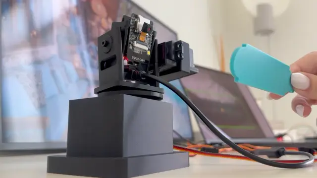 Camera Bots
ESP32-CAM AI Object Tracking Camera
$50ESP32-CAM AI Object Tracking Camera A DIY pan/tilt camera that finds a custom target object with a trained YOLO model and physically turns to follow it. An ESP32-CAM streams live video over Wi-Fi to a laptop; Python runs the YOLO detector and sends movement deltas over serial to a second ESP32-WROOM-32 board, which drives two servos through a PCA9685 driver. All mechanical parts are 3D printed from an OpenSCAD source, so the mount can be resized for different servos and camera boards. This is orobot's first entry combining on-device Wi-Fi video streaming with a trained computer-vision model driving physical actuators — most of the catalog's vision work is closed-loop on a single board; this one splits video capture (ESP32-CAM), inference (laptop/YOLO), and actuation (second ESP32 + PCA9685) across three hops. How It Works What You'll Need ESP32-CAM module (the video source) ESP32-WROOM-32 DevKit board (the servo controller) PCA9685 16-channel PWM/servo driver 2x MG995/MG996-style servos (pan + tilt) External 5V power supply for the servos Jumper wires, M3 screws, micro screws for the ESP32-CAM module 3D-printed mount parts (STLs included; OpenSCAD source included for resizing) A laptop to run the Python + YOLO tracking script Build Notes The servos are powered externally at 5V — the ESP32 shouldn't power them directly, they draw more current than its regulator is rated for. I2C wiring: ESP32 GPIO21 -> PCA9685 SDA, GPIO22 -> PCA9685 SCL. All grounds must be tied together (ESP32, PCA9685, and the external 5V supply). The trained YOLO model () was trained on a custom 3D-printed target object — swap in your own dataset via and to track something else. For real-time tracking, a smaller/faster video stream tracked better than a high-resolution one with too much latency — the source project runs the ESP32-CAM at a reduced frame size for this reason. This is an actively-evolving prototype per the source author — movement smoothing, wiring, and the printed parts are still being refined upstream. orobot Learning Interface The orobot program here exposes the pan and tilt axes as motor slots you can jog directly from the browser (joystick, center button, scan sweep) to learn the control surface. The full AI tracking loop (YOLO inference + serial bridge) still runs on your own machine per the source repo's Python setup — this program is a hardware-control on-ramp, not a port of the vision pipeline. Attribution Creator: mmm1712 Source: github.com/mmm1712/ESP32-CAM-AI-Object-Tracking Commit: e7a6c06c9986dae844f30cb7bdddff821d888e5d License: Shared by the author for learning and experimentation (no formal OSS license file in the source repo — confirm terms with the author before commercial use)
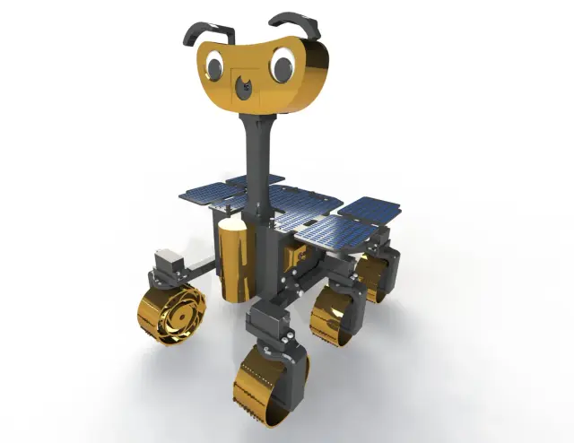 Mobile Robots
ExoMy
$550ExoMy is a low-cost, 3D-printed Mars rover replica developed by the European Space Agency's Planetary Robotics Laboratory. It reproduces the rocker-bogie suspension used by real Mars rovers (Sojourner, Spirit/Opportunity, Curiosity, Perseverance) at a build cost of roughly 500 EUR, using a Raspberry Pi 4 and hobby servos instead of flight hardware. ExoMy drives on six independently steerable/driven wheels and supports three locomotion modes: Ackermann (car-like curves), Point/Spot Turn (rotate in place), and Crabbing (sideways translation without changing heading). Control is via a built-in web UI (WiFi, works from any browser) or a USB gamepad, with a live camera feed from the onboard Raspberry Pi Camera V2. The rover's head has interchangeable 3D-printed hats, eyes and mouths for a bit of personality, and the whole build — chassis, bogies, wheels, head, and 20+ optional decorative parts — is documented with drawings, wiring diagrams, and a step-by-step assembly wiki. Attribution Design, hardware, software, documentation and photography by the ESA Planetary Robotics Laboratory (Maximilian Ehrhardt, Miro Voellmy, Lorenzo Cervantes and contributors). Licensed under GPL-3.0. Source: github.com/esa-prl/ExoMy (hardware/docs) and github.com/esa-prl/ExoMySoftware (control software). Docs site: esa-prl.github.io/ExoMy. If you use ExoMy in an academic context, cite: M. Voellmy and M. Ehrhardt, "ExoMy: A Low Cost 3D Printed Rover," i-SAIRAS 2020. Hardware Computer: Raspberry Pi 4 Model B + Adafruit 16-Channel PWM/Servo HAT (PCA9685) Actuators: 12x Parallax servos — 6 continuous-rotation drive servos (one per wheel) + 6 steering servos (rocker-bogie corner steering) Camera: Raspberry Pi Camera Module V2 Power: 3S LiPo battery (11.1V, 3000mAh) through a step-down DC-DC converter, with a battery-voltage alarm Chassis: fully 3D-printed rocker-bogie frame, wheels, and head/body panels This program is a learning-oriented control interface, not a port of ExoMy's full ROS-based software stack (locomotion kinematics, joystick mapping, web GUI). For the real flight software, see the ExoMySoftware repository — it runs in Docker on the Pi and implements the full Ackermann/point-turn/crabbing kinematics. Photos IRL build photos (ESA Planetary Robotics Laboratory, from the project wiki, used with attribution).
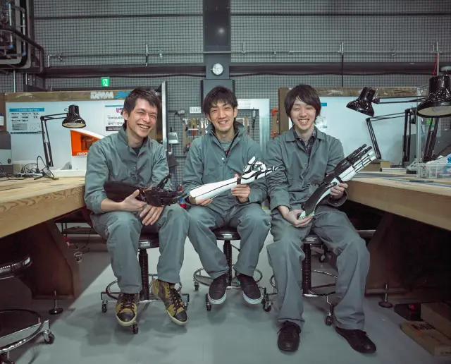
HACKberry
$160Browse by type
Browse by hardware
Browse by difficulty