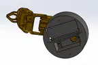
5-DOF IoT Robot Arm
 O
OAbout this program
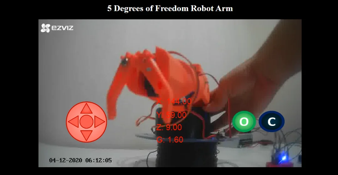
An open-source 5-degree-of-freedom robot arm you build, print, and control from a browser over WiFi — with a live IP-camera video feed of the arm as you drive it.
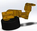
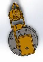
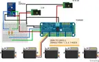
The arm is 3D printed and actuated by 5 hobby servos (2x MG996R for the base/shoulder, 3x SG-90 for the elbow/wrist/gripper) driven by a PCA9685 16-channel PWM driver. An ESP8266-01s microcontroller joins your WiFi network and talks to a small NodeJS web server over Socket.IO, which streams commands out to the arm and relays a live RTSP camera feed back to the browser. The server computes inverse kinematics (Denavit–Hartenberg parameters) so you can jog the end effector in X/Y/Z instead of driving each joint by hand, and it rejects moves outside the arm's reachable workspace.
Originally built as an educational robotics + web-programming project by Victor Cadillo Guzman.
Attribution & License
- Creator: Victor Cadillo Guzman (vcadillog)
- Source: https://github.com/vcadillog/3D-printed-IoT-Robot-Arm-5DOF-NodeJS
- No explicit license file in the source repository — verify terms with the author before redistributing derivative hardware/software commercially.
What you'll need A 3D printer, an ESP8266-01s (or compatible ESP8266 module with 2+ GPIO), a PCA9685 servo driver, 5 hobby servos, an IP camera, a 5V/5A power supply with a 5V→3.3V step-down converter, and a computer (a Raspberry Pi works) to run the NodeJS web server.
Note on orobot platform support: this design's control stack (ESP8266 + PCA9685 + a standalone NodeJS/Socket.IO app) is not orobot-firmware-native — it runs its own server outside the orobot device pipeline. This Program is a learning/reference entry point; treat the code tab as illustrative of the orobot Program IDE model (motors/poses/sequences), not a 1:1 port of the original inverse-kinematics control loop. Build and run the original from source (see GitHub link) for the full IP-camera + IK experience.
🖨 Print Files (7)
BASE.STL
DOF-2.STL
DOF-3.STL
DOF-4.STL
DOF-5.STL
GRIPPER.STL
Required Hardware
| Item | Qty | Notes |
|---|---|---|
| ESP8266-01s (or compatible ESP8266 module, 2+ GPIO) | 1 | WiFi microcontroller, talks to the web server over Socket.IO |
| Servo Motor MG996R | 2 | Base + shoulder joints (higher torque) |
| Servo Motor SG-90 | 3 | Elbow, wrist, gripper joints |
| PCA9685 16-channel PWM/Servo Driver | 1 | I2C servo driver board |
| IP camera (RTSP-capable) | 1 | Live video feed relayed to the browser UI |
| 5V, 5A DC power source | 1 | Powers the servo bank |
| 5V→3.3V step-down converter | 1 | Steps power down for the ESP8266 |
| 330Ω resistor | 2 | Logic-level protection on I2C lines |
| M3 Allen bolt | 12 | Mounts the first 2 DOF + PCA9685 |
| Protoboard | 1 | Wiring breadboard for ESP8266/PCA9685 |
| Computer / Raspberry Pi — runs NodeJS + ffmpeg | 1 | Hosts the web app and RTSP-to-browser video relay |
| 3D printer + filament | — | Prints all 7 STL body parts |