
Spot Micro Quadruped
 B
B✓ リンク確認済み Aug 31, 2026
インストールするには登録してくださいこのプログラムについて
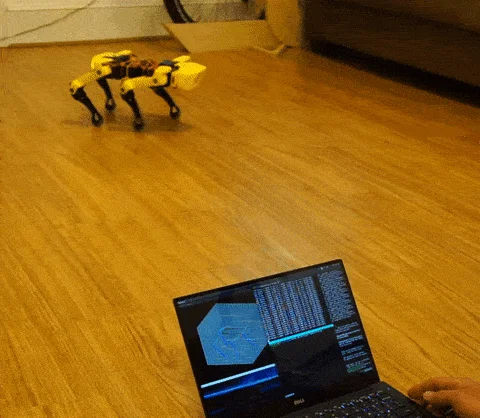
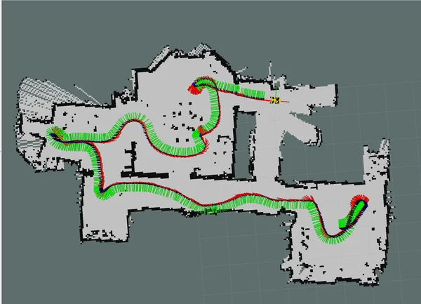
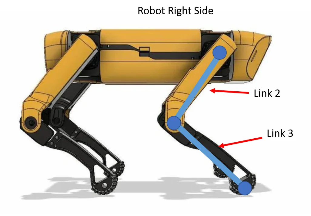
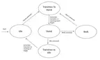
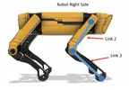
Spot Micro is a 4-legged open-source quadruped robot inspired by Boston Dynamics' Spot. Created by mike4192 in 2020, the project implements full motion control on a 3D-printed Spot Micro frame, including sit, stand, body angle, and walking gaits. Supporting libraries provide additional capabilities such as SLAM mapping using a body-mounted RPLidar.
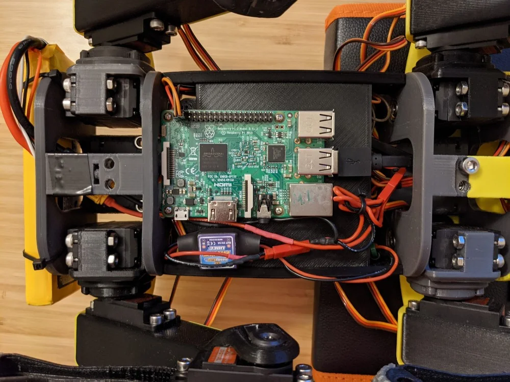
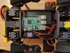
The robot uses a Raspberry Pi 3B running Ubuntu 16.04 with ROS Kinetic. Twelve PDI-HV5523MG servos (3 per leg) drive the legs through a PCA9685 i2c servo control board. The default 8-phase gait incorporates body movement to maintain balance and stability; an alternate trot gait achieves faster walking speeds.
The 3D-printed frame originates from KDY0523's Thingiverse "Spot Micro" design (thing:3445283). This repository contributes the ROS-based motion control software, kinematics implementation, custom shoulder mounts, lidar mount, and SLAM integration on top of that frame.
Hardware
| Component | Notes |
|---|---|
| Computer | Raspberry Pi 3B |
| Servo controller | PCA9685 (i2c) |
| Servos | 12 x PDI-HV5523MG (or HV5523MG / cls6336hv) |
| LCD panel | 16x2 i2c (optional) |
| Battery | 2s 4000 mAh LiPo |
| UBEC | HKU5 5V/5A regulator |
| Lidar | RPLidar A1 (for SLAM) |
| Frame | KDY0523 Spot Micro on Thingiverse |
Estimated cost: $300-450 USD. Build time: 2-4 weeks. Skill level: Intermediate to Advanced (requires familiarity with ROS, Linux, and 3D printing).
Software architecture
The project is structured as a ROS Catkin workspace. Key nodes:
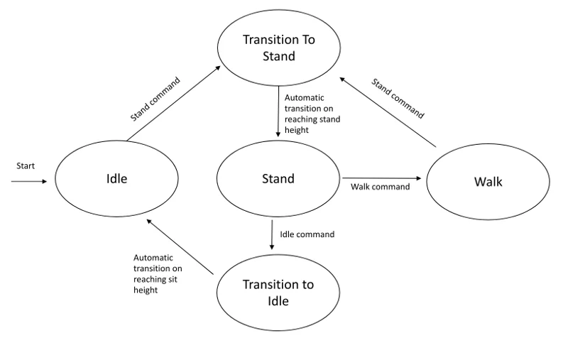
- spot_micro_motion_cmd — main C++ motion control node implementing kinematics, gaits, and state machine
- ros-i2cpwmboard — PCA9685 servo driver, controlled via i2c
- spot_micro_keyboard_command — Python keyboard teleop
- spot_micro_joy — joystick teleop
- servo_move_keyboard — manual servo calibration utility
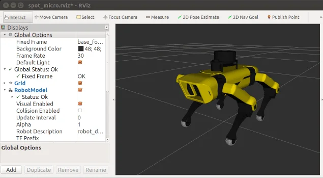
- spot_micro_rviz / spot_micro_plot — visualization
- lcd_monitor — LCD status display
Firmware status
This program is BYOD (bring-your-own-device). The motion control runs on a Raspberry Pi with ROS, not on the orobot platform's native firmware. The orobot.io program here serves as a learning entry point and command interface; full hardware control requires checking out the GitHub repository, building the catkin workspace, and flashing the configured Pi image. See the project README for setup instructions.
Attribution
Source: https://github.com/mike4192/spotMicro Author: mike4192 License: MIT Frame design: KDY0523 (Thingiverse thing:3445283, separate license)
Printing
The print set is the 13 canonical SpotMicro parts from the upstream mike4192/spotMicro spot_micro_rviz/urdf/stl/ set. Because this is a 12-DOF quadruped (four identical-per-side legs), note the print quantities below — the static list shows each file once.
Body (print x1 each):
mainbody.stl— central body shellfrontpart.stl— front body sectionbackpart.stl— rear body sectionfoot.stl— base/floor plate
Left legs (print x2 each — 2 left legs):
lshoulder.stl,larm.stl,larm_cover.stl,lfoot.stl
Right legs (print x2 each — 2 right legs):
rshoulder.stl,rarm.stl,rarm_cover.stl,rfoot.stl
Left and right leg parts are true mirrors, not interchangeable — print two of each side for the four legs (3 servos per leg = 12 DOF). One MG-class servo (PDI-HV5523MG) goes in each joint.
Optional:
rplidar_main.STL— RPLidar A1 mount, only needed if you add the body-mounted lidar for SLAM. Skip it for a walk-only build.
Cleanup note: the imported list previously held 39 files — the 13 real parts plus 26 duplicate re-imports that all carried opaque orobot-upload-<UUID>.stl names (each of the 13 parts was triplicated). The duplicates were verified by byte-size match against the upstream STLs and removed, leaving the clean, human-readable 13-part set. The 3D-printed frame derives from KDY0523's Thingiverse design (thing:3445283); servos, Pi, PCA9685, lidar, and battery are sourced from the BOM, not printed.
必要なハードウェア
| Item | Qty | Unit Cost | Notes |
|---|---|---|---|
| Raspberry Pi 3B (or 3B+) | 1 | $40 | Main controller running ROS |
| PCA9685 16-channel PWM/servo driver board | 1 | $10 | I2C servo control |
| PDI-HV5523MG digital servo (high-voltage, 23 kg-cm) | 12 | $25 | 3 per leg x 4 legs |
| 2S 4000 mAh LiPo battery (7.4V) | 1 | $25 | Direct power to servo bus |
| HKU5 5V/5A UBEC voltage regulator | 1 | $10 | Powers Pi from LiPo |
| RPLidar A1 360-degree lidar | 1 | $99 | Optional but used in repo |
| 16x2 I2C LCD panel | 1 | $8 | Optional status display |
| F625ZZ shielded ball bearings (5x16x5 mm) | 4 | $1 | Shoulder assembly |
| M3x10 socket-head screws + M3 nuts | 8 of each | $0.10 | Shoulder assembly |
| M2.5x8 screws | 4 | $0.10 | RPLidar mount |
| Jumper wire / Dupont cable assortment | 1 set | $7 | I2C, signal wiring (inferred) |
| XT60 connector + battery harness | 1 | $5 | LiPo connection (inferred) |
| LiPo balance charger (2S/3S) | 1 | $25 | Charge battery (inferred) |
| Double-sided foam mounting tape | 1 roll | $5 | Platform adhesion |
似たロボットを探す