Ball-Balancing Stewart Platform
 B
BÜber dieses Programm
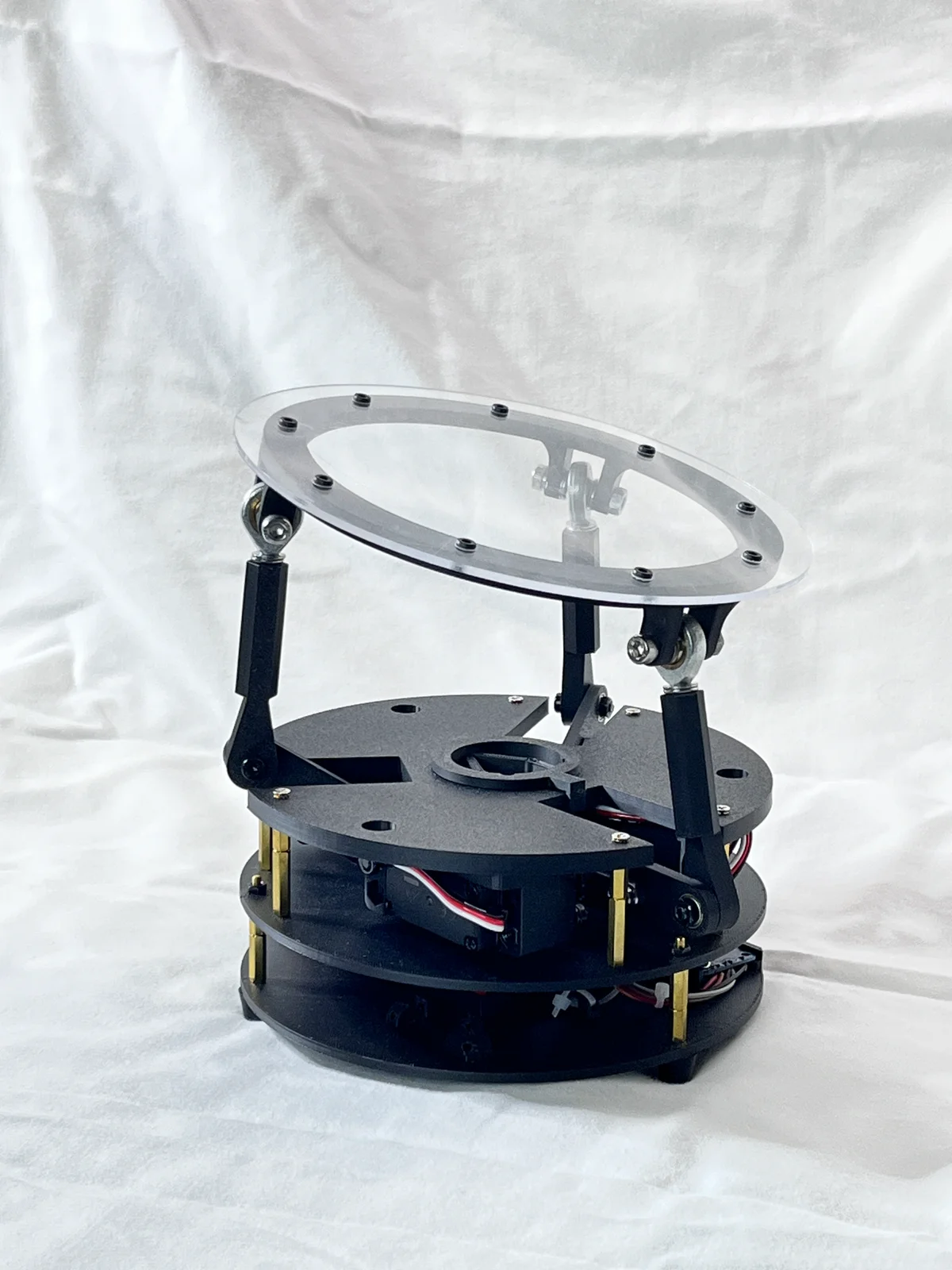
Ball-Balancing Stewart Platform — an educational 3-DOF parallel-kinematics robot that balances a ball on a tilting plate using computer vision and PID control.
A Raspberry Pi camera watches a ball rolling on a top plate; a PID controller (PID.py) converts the ball's tracked (x, y) offset from center into a tilt command, and inverse kinematics (robotKinematics.py) solves the three platform-servo angles needed to produce that tilt via a Stewart-platform-style parallel linkage (3 servos driving a top plate through ball-jointed links, PCA9685 servo driver).
How it works:
camera.pycaptures frames via Raspberry Pi Camera (picamera2) and tracks the ball by color/darkness thresholding in HSV + grayscale.PID.pycomputes a tilt angle/direction (theta/phi) to correct the ball's position toward center.robotKinematics.pysolves inverse kinematics for the 3-servo Stewart-platform mechanism.controller.pydrives the 3 servos (via an Adafruit PCA9685 PWM driver / ServoKit) to the computed angles, interpolating smoothly between positions.
A Flask web app (app.py + templates/index.html) also exposes manual sliders for direct tilt control, independent of the camera/PID loop.
Attribution & Source: Created by I-M-Robotics-Lab — source repository: https://github.com/I-M-Robotics-Lab/Ball-Balancing-Robot. Discord: https://discord.com/invite/WJuUWsy6DJ. Printable 3D models and Bambu A1 print profile: https://makerworld.com/en/models/1197770-ball-balancing-robot
License: GPL-3.0 (GNU General Public License v3.0). This is a strong copyleft license — any derivative hardware/software you distribute must also be licensed under GPL-3.0 and its source made available. Verify GPL-3.0 compatibility before commercial use.
This orobot.io program is a learning-stub control interface only — it exposes direct manual servo control (see script.js) and does not port the real camera + PID + inverse-kinematics balancing loop from the source repo, which requires a Raspberry Pi with a camera and custom Python firmware (BYOD, not yet supported by orobot-firmware). Build the physical robot and run the original Python code from the source repo for the actual self-balancing behavior.
3D-printed parts uploaded here are machine-tessellated from the author's STEP CAD files (via OpenCASCADE, one STL per solid) since the repo ships CAD sources rather than pre-sliced STLs — spot-check mesh quality before printing/publishing.
🖨 Druckdateien (9)
Barrel_Jack_Cover-v1.stl
Base-v9.stl
Bottom-v2.stl
Link1-v7.stl
Link2-v9.stl
Middle-v2.stl
Mount_5mm.stl
top_panel-v5.stl
top_ring-v2.stl
Benötigte Hardware
| Item | Qty | Notes |
|---|---|---|
| Raspberry Pi (model unspecified) | 1 | Runs main.py / app.py; needs a CSI camera port for Picamera2 — verify exact Pi model (3B+/4/5) used by the author |
| Raspberry Pi Camera Module (Picamera2-compatible) | 1 | Overhead ball-tracking camera; code uses picamera2 — verify exact camera module (v2/v3/HQ) |
| Adafruit 16-Channel PWM/Servo Driver (PCA9685) | 1 | Code imports adafruit_pca9685 and drives 3 servos via ServoKit(channels=16) — verify exact board (HAT/Bonnet vs. breakout) |
| Standard hobby servo, ~270° range | 3 | actuation_range = 270, PWM 500–2500us; wired to PCA9685 channels 13/14/15 — verify exact servo model/torque |
| 5V power supply, barrel-jack | 1 | Repo includes a printed "Barrel_Jack_Cover" part implying barrel-jack DC input — verify voltage/current rating |
| M2 x 8 Cap Head Socket Screw | 6 | |
| M2.5 x 10 Cap Head Socket Screw | 4 | |
| M3 x 5 Socket Head Screw | 18 | |
| M3 x 10 Socket Head Screw | 3 | |
| M3 x 15 Socket Head Screw | 1 | |
| M3 x 20 Socket Head Screw | 3 | |
| M4 x 20 Socket Head Screw | 6 | |
| M4 x 30 Socket Head Screw | 6 | |
| M5 x 30 Socket Head Screw | 3 | |
| M3 Hex Nut | 3 | |
| M4 Nylock Nut | 6 | |
| M4 Hex Nut | 12 | |
| M3 x 10 Standoff | 9 |
Ähnliche Roboter entdecken