Self-Balancing Robot
 B
B✓ Links verified Oct 9, 2026
Sign up to InstallAbout this program
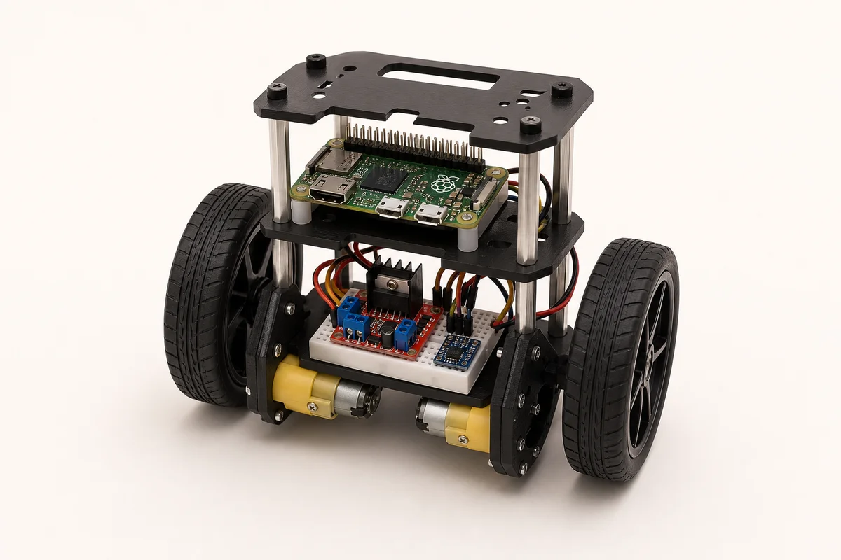
Hero image: AI-generated illustrative render — not a photo of a real build. See the Attribution section below for design references and upstream photos.
A 3D-printable two-wheeled self-balancing robot — the classic inverted-pendulum control theory demo you can actually build and drive from a browser. The robot stays upright using a PID control loop fed by an MPU-6050 IMU, with two N20 DC gear motors driven through an L298N motor driver on a Raspberry Pi Zero 2 W.
What makes this interesting: PID tuning happens live in the browser — drag the P, I, and D sliders while the robot runs and watch it respond. Abstract control theory becomes tactile and immediate.
What It Does
- Balances on two wheels using a PID loop (proportional-integral-derivative controller)
- Accepts forward/backward/turn commands from the browser while it actively balances
- Live telemetry: real-time angle, motor speeds, and PID terms visible in the control panel
- PID gain sliders: adjust P, I, and D from the browser with immediate effect
- Falls gracefully: motors cut when tilt exceeds 45° (safe-stop threshold)
Hardware
- Raspberry Pi Zero 2 W (runs Python PID loop + orobot firmware)
- MPU-6050 IMU on I2C bus — reads tilt angle at ~200 Hz via complementary filter
- L298N dual H-bridge motor driver — PWM drive to two N20 6V DC gear motors
- 2× N20 DC gear motor with wheel mounts and 3D-printed wheels
- LiPo 7.4V 2S battery pack (or 2× 18650 in series)
- 3D-printed chassis — Thingiverse model #1069256 or compatible
Build Overview
- Print the chassis (PLA, 0.4mm nozzle, 20% infill). Total print time ~3–5h.
- Mount motors and wheels in the chassis motor pockets.
- Wire MPU-6050 to Pi GPIO I2C (SDA=BCM 2, SCL=BCM 3); power from 3.3V.
- Wire L298N: IN1=BCM 17, IN2=BCM 27 (left), IN3=BCM 22, IN4=BCM 23 (right); ENA/ENB=BCM 12/13 (PWM).
- Install Pi firmware with smbus2 and RPi.GPIO libraries.
- Set balance_angle (the equilibrium tilt offset for your specific build — usually ±3° from level).
- Connect in orobot, deploy this program, and start tuning PID gains from the browser.
Tuning Guide
Start with D=0, I=0, and increase P until the robot starts to oscillate. Then back P off 20%, add a little D to damp oscillation, and finally a small I to correct steady-state lean. Typical starting values: P=80, I=5, D=2 for N20 motors at ~6V. Your mechanical build will differ — expect to spend 30 minutes tuning.
Honest Expectations
The balance loop runs on the Pi at ~50 Hz. If the Pi is busy (e.g., SD card writes, heavy CPU), the loop rate drops and the robot falls. Use a fast SD card or run from a USB drive. The orobot browser interface adds a few hundred milliseconds of latency for manual drive commands, which is fine — the Pi handles the balance loop autonomously; browser commands are just setpoint offsets.
Attribution
This program is an original orobot design guide for the self-balancing robot class. Hardware inspiration from the B-ROBOT by JJRobots (GPL-2.0, https://github.com/jjrobots/B-ROBOT) and the 3D-printable Arduino Nano 33 BLE design featured on Hackaday (December 2022, https://hackaday.com/2022/12/27/3d-printed-self-balancing-robot-brings-control-theory-to-life/). The orobot control code is original (MIT).
Required Hardware
| Part | Qty | Unit Cost | Notes |
|---|---|---|---|
| N20 DC Gear Motor 6V 200RPM + wheels | 2 | ~$4 | Any N20 variant with ~200RPM at 6V |
| L298N Dual H-Bridge Motor Driver | 1 | ~$2 | Any L298N board works |
| MPU-6050 6-DOF IMU | 1 | ~$1 | I2C; 3.3V compatible |
| Raspberry Pi Zero 2 W | 1 | $15 | Main compute; Pi 3/4 also works |
| 7.4V LiPo 2S battery (1200–2200 mAh) | 1 | ~$10 | Or 2× 18650 in a 2S holder |
| 5V DC-DC converter (for Pi power) | 1 | ~$2 | Step-down from 7.4V to 5V |
| PLA filament for chassis | 1 | ~$3 | ~80g for full chassis |
| M2/M3 bolts and nuts | 1 set | ~$2 | Chassis assembly |
| Jumper wires | 1 set | ~$1 | Pi to L298N and MPU-6050 |
| Total | — | ~$40–45 | Build one robot |
Explore similar robots