3D Print Open Source AI Robots
 Mobile Robots
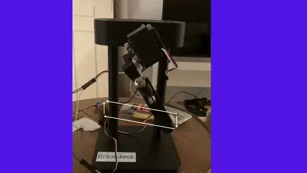
Botzo Quadruped
$320Autonomous quadruped robot built under 500€ to navigate and interact
 Mobile Robots
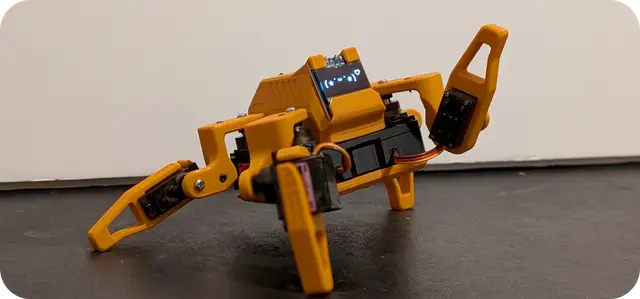
Sesame Quadruped
$851,619 stars on GitHub. Sesame is an affordable, open-source mini quadruped robot powered by an ESP32 microcontroller. Designed by Dorian Borian, Sesame uses 8 MG90S metal-gear servos (two per leg) for 8-DOF locomotion and features a 128×64 OLED display that serves as an expressive robot face. Source: https://github.com/dorianborian/sesame-robot All mechanical parts are fully 3D-printable on a standard FDM printer. The hardware folder contains both parametric STEP and Fusion 360 source models alongside the STL files, allowing full customization. The frame, internal structure, covers, and leg segments are all available as individual STLs. The ESP32 firmware handles inverse kinematics, face animations on the OLED display, and a WiFi-based control interface accessible from any browser. A desktop companion app (Sesame Studio) is included for easy gait configuration and pose tuning without writing code. Community documentation covers full assembly with detailed wiring diagrams and a comprehensive BOM. Hat variants are available (enclosed, open, cat ears) for personality customization. With over 1600 GitHub stars, Sesame has become a go-to beginner quadruped platform. License: Apache 2.0.
 Mobile Robots
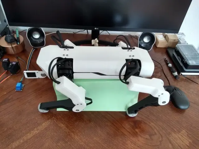
SpotMicro ESP32
$130377 stars on GitHub · michaelkubina/SpotMicroESP32 SpotMicroESP32 is Michael Kubina's redesign of the SpotMicro quadruped, derived from KDY0523's original Thingiverse design, optimized for support-free 3D-printing and built around an ESP32-DevKitC. 12-DOF (3 servos per leg). Source: https://github.com/michaelkubina/SpotMicroESP32 SpotMicro family — pick your compute target: | Variant | Controller | ROS | |---------|-----------|-----| | SpotMicro (Pi) — mike4192 | Raspberry Pi | ROS Kinetic | | SpotMicro Jetson Nano | Jetson Nano | ROS Melodic | | SpotMicro ESP32 (this) | ESP32-DevKitC | No ROS | Hardware: 12 servos (3 per leg: shoulder yaw, upper, lower) ESP32-DevKitC main controller Optional ESP32-CAM for vision LiPo battery with custom mounting brackets Software ecosystem (community forks): Maarten Weyn BLE/IK firmware: https://github.com/maartenweyn/SpotMicroESP32 Blacksheep Nitro Fork (PCB + walking gait + RC): https://github.com/Blacksheep909/SpotMicroESP32-Nitro-Fork SpotMicro-Leika (FreeRTOS + 2 gaits): https://github.com/runeharlyk/SpotMicroESP32-Leika SpotMicroAI Community: https://spotmicroai.readthedocs.io/ Resources: Thingiverse: https://www.thingiverse.com/thing:4559827 Original SpotMicro by KDY0523: https://www.thingiverse.com/thing:3445283 Printing SpotMicro is a 12-DOF quadruped — 4 legs, 3 servos each — so the shoulder and limb parts must be printed once per leg (×4), and the chassis side is printed as a left/right pair (×2). This is the support-free Kubina redesign, so no supports are needed. Print quantities: ChassisSide ×2; FrontCover ×1, RearCover ×1, Cameramount ×1. Per leg (×4 each): BottomShoulder, InnerShoulder, OuterShoulder, LimbBallBearingMount, LimbBottomShell, LimbTopShell, LimbServohornMount, FootTip. Note on RearCover: the file is labelled a "Template." It is a customizable base cover meant to be edited (e.g. to add a cutout for your specific electronics/port layout) before printing, rather than a fixed final part — print it as-is if you don't need a custom opening. The upstream source also includes many experimental and alternate variants (different power-board mounting plates, optimized covers, mold parts); those are optional alternates and are intentionally excluded from this set, which is one clean buildable SpotMicro.
 Mobile Robots
Yertle Quadruped
$350Yertle — A 3D Printed Quadrupedal Robot for Locomotion Research Yertle is a 12-DOF quadruped robot designed for locomotion research. It fuses the leg geometry of the Kangal quadruped with the body geometry of SpotMicro, making most parts cross-compatible with the SpotMicro ecosystem. Creator: Jerome Alexander Graves · License: MIT · Status: Work-in-progress (functional; ROS2 integration pending) This Program is a learning entry point. The original firmware is C++ on an ESP32 with a Python GUI master controller — the orobot Program here exposes a stubbed JavaScript interface so you can explore the gait/command surface in-browser. To run on real hardware, follow the upstream build and flash instructions. Mechanical 4 legs × 3 DOF (hip yaw + hip pitch + knee) = 12 servos total Leg extension: ~20 cm Mass: ~1.8 kg Frame: PLA or ABS, printable on a 150 × 150 mm bed (Ender 3 Pro tested) Print time: ~2 weeks (5–10 h/day on a single Ender 3 Pro) 3D-Printed Parts This is the complete set of 21 unique parts: the four-piece outer Shell (Top, Bottom, Front, Back), the Frame (shoulder frames, servo mounts, body beams, electronics plate), and the Legs. Yertle is a 4-legged, 12-servo (3-DOF-per-leg) quadruped, so the leg and shoulder parts must be printed in multiples. Recommended material: PLA or ABS; a build plate of at least 150mm is needed for the larger parts. Print quantities (per the upstream build guide): Shell — Top Shell ×1, Bottom Shell ×1, Front Shell ×1, Back Shell ×1 (print these in a second color if you want a two-tone body). Frame — Inner Shoulder Frame ×2, Outer Shoulder Frame ×2, Upper Shoulder Frame ×2, Lower Shoulder Frame ×2, Left Servo Mount ×2, Right Servo Mount ×2, Servo Mount Top Bracket ×4, Side Body Beam ×2, Electronics Mounting Plate ×1. Legs (one set per leg, ×4 legs) — Femur ×4, Femur Servo Connector ×4, Inner Tibia ×4, Outer Tibia ×4, Short Link ×4, Long Link ×4, Left Shoulder ×2, Right Shoulder ×2. Software Architecture Master/slave over serial or UDP/WiFi: Slave (ESP32, C++/Arduino): servo control, sensor read, inverse kinematics, safety limits. Master (Python 3 GUI): gait generation, sensor fusion, ROS2 (todo). Runs on anything with WiFi + screen + Python 3. Simulation: Python-based built-in simulator; URDF available for Gazebo/Unity. Build Cost ~$315–350 total (servos dominate at ~$200). See full BOM in the upstream Design/README. Hardware Compatibility (BYOD) Yertle is not an orobot-firmware-native build. It uses a custom ESP32 firmware. Running the orobot Program against real hardware requires bridging the orobot WebSocket protocol to Yertle's UDP master/slave protocol — a custom integration tracked under the orobot ESP32 BYOD effort. Inspirations Kangal (leg design) SpotMicro (body geometry, parts compatibility) Open Quadruped Links GitHub Repository STL Files Design/README & BOM ESP32 Firmware Python Master GUI URDF / Simulation --- Extracted from commit on 2026-04-27.
 Mobile Robots
Kame32
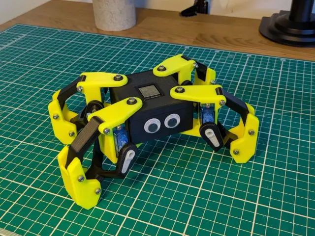
$50Kame32 is an open-source quadruped walking robot by JavierIH. Built around an ESP32 and 8 servo motors, it walks, runs, dances, and performs a rich library of quadruped gaits — all controlled wirelessly via a built-in web-based gamepad over Wi-Fi. All structural parts are 3D-printable. A custom PCB (KiCAD gerbers included) centralizes servo wiring. Choose MG90S (higher torque) or SG90 servos — brackets for both variants are included. Specifications | Property | Value | |----------|-------| | Motors | 8 servos (MG90S or SG90) | | DOF | 8 (2 per leg) | | Controller | ESP32 Dev Kit | | Control | Web gamepad via Wi-Fi | | PCB | Custom KiCAD design (gerbers included) | | CAD | FreeCAD source file | | Build time | 1–2 weekends | | Skill level | Intermediate | Gaits Walk · Backward · Run · Omni Walk · Turn Left · Turn Right · Moonwalk · Dance · Up/Down · Push Up · Hello · Jump · Home All gaits use the Octosnake oscillator library — sinusoidal servo control with per-axis phase offsets. Hardware ESP32 drives 8 PWM servos at 50 Hz / 16-bit resolution. Per-servo calibration offsets stored in ESP32 NVS. Firmware PlatformIO / Arduino. Build environments: calibration (tune offsets) and gamepad (web UI controller). Attribution Creator: JavierIH Source: github.com/JavierIH/Kame32 License: CC BY-SA 4.0 (hardware) - GPL-3.0 (code) Build Guide Source repository with CAD, firmware, and assembly files: github.com/JavierIH/Kame32 Printing Kame32 is an 8-servo quadruped — 2 servos per leg, 4 legs. The servo brackets and legs come in two versions matched to the servo you use: SG90 (plastic-gear) or MG90S (metal-gear). This Print All set uses the SG90 version, which is the default servo in the bill of materials; MG90S is listed there only as an optional higher-torque upgrade. The four MG90S-specific files have been removed so the list yields one buildable robot rather than two overlapping servo sets. Print quantities: print body-box and body-cover once each (the chassis). The leg and bracket parts are per-leg, so the left/right SG90 leg and bracket files are each printed in multiples to cover all four legs (the robot has 4 legs, each with a left and right side); print the shared leg-link, bushing, and foot parts in matching multiples. Build one full set of leg hardware per leg from the mirrored left/right SG90 parts. Note: if you are building with MG90S metal-gear servos instead, use the corresponding -mg90s bracket and leg files from the upstream source (github.com/JavierIH/Kame32) in place of the -sg90 parts.
 Home Automation
DIY SmartLock
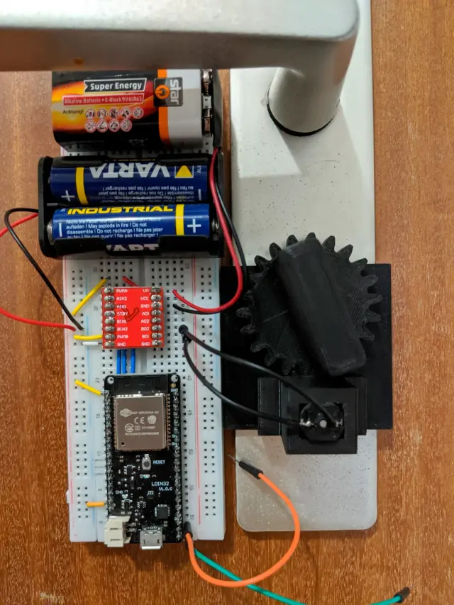
$37DIY SmartLock A battery-powered 3D-printed smart lock powered by an ESP32 and driven by an N20 geared motor. Designed for residential door locks, it replaces the manual key turn with touch-triggered automation — touching the metal door knob from outside wakes the ESP32 from deep sleep and checks MQTT for authorization before unlocking. How It Works The ESP32 spends nearly all of its time in deep sleep (as low as 5.2 µA on bare ESP32), waking only when the capacitive touch sensor detects contact with the door knob. On wake it connects to WiFi, subscribes to an MQTT topic (door/auth), and drives the N20 motor clockwise or counter-clockwise to lock or unlock. The system integrates naturally with Node-RED, Home Assistant, or any MQTT-capable automation stack for presence-based auto-auth. Important: The N20 motor must operate at 9 V — 3–6 V versions will not reliably actuate the door trap. Specifications | Property | Value | |---|---| | Controller | ESP32 (bare WROOM-32 or LOLIN D32) | | Motor | N20 geared DC motor (9 V, ~40 mA no-load) | | Motor Driver | TB6612FNG (direct GPIO control) | | Power — Logic | 2x AA alkaline batteries (~3.2 V) | | Power — Motor | 9 V block battery | | Deep Sleep Current | ~5.2 µA (bare ESP32), 125 µA (LOLIN D32) | | Wake Trigger | Capacitive touch sensor (ESP32 pin T2) | | Connectivity | WiFi 802.11 b/g/n + MQTT | | Printed Parts | 4 STLs (base, gear-motor, cage-motor, gear-key-knob) | | Build Difficulty | Intermediate | | Firmware | Arduino / PlatformIO | Attribution Designer: Florian Vogler (@vogler on GitHub) Source: https://github.com/vogler/SmartLock License: Source-available (no explicit open-source license — check repo for usage terms) 3D Model: https://a360.co/4lLHHwa (Fusion 360, downloadable in multiple formats) Build Album: https://photos.app.goo.gl/bewiZ1qH8sHnJjmg7 Printing Print one of each of the four parts: 1-base (the mounting base), 2-gear-motor (motor drive gear), 3-cage-motor (motor cage/housing), and 4-gear-key-knob (the key knob gear). Together these make one complete SmartLock mechanism. Note: the upstream source also includes a file named 0-SmartLock-assembled, which is a fully assembled preview model of the whole lock — it is a visual reference for how the parts fit together, not a printable part. It has been excluded from this Print All set so the list yields exactly the parts you need to build the lock.
 Mobile Robots
Hexapod
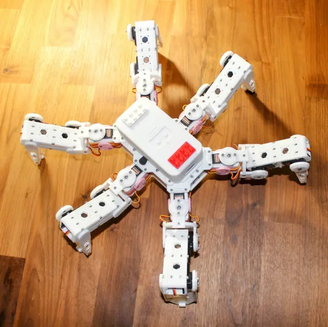
$120Hexapod — 3D Printed Six-Legged Walking Robot A fully 3D-printed hexapod robot with 18 servo motors (three per leg) providing lifelike, agile locomotion. Designed by rookidroid.com, this project uses either an ESP32 or Raspberry Pi Pico W/2W controller board with built-in WiFi for wireless remote control. The firmware supports over-the-air (OTA) updates so you can iterate on motion patterns without touching the hardware. Hexapod v2 is the recommended build. The original v1 used MG90S servos which are prone to failure; v2 upgrades to stronger 21G DS Power/Miuzei servos and is significantly more reliable. Do not use MG90S. Note: The controller board is proprietary to rookidroid.com. A generic ESP32 dev board can substitute — check the firmware docs for pin mapping. Specifications | Property | Value | |----------|-------| | Legs | 6 | | Servos | 18 x 21G (3 per leg: hip, knee, ankle) | | Controller | ESP32 or Raspberry Pi Pico W/2W | | Communication | WiFi (UDP port 1234) + OTA updates | | Power | 2 x 18650 Li-ion cells | | Printed Parts | 20 STLs, all print without supports | | Print time | ~40–60 hours total | | Skill level | Intermediate | Motion Modes The ESP32 firmware implements a pre-computed look-up-table gait system with 18 motion modes including: directional walking at 0, 45, 90, 135 degrees (left and right variants), 180 degrees; fast forward and backward; turn left and right; climb forward and backward; body rotations on X, Y, Z axes; and a twist mode. Attribution Creator: rookidroid.com Source: https://github.com/rookidroid/hexapod License: GNU GPL v3 Printing This is a complete, modular set of 20 unique parts. Because the hexapod has 6 identical legs (each with 3 joints), many parts must be printed in multiples. Per the upstream build guide, print the following quantities: Body (print once each): bodybase ×1, bodytop ×1, bodytopcover ×1, bodybattery ×1. Body (print in pairs): bodyside ×2, bodyfrontback ×2. Servo brackets (one per leg): bodyservoside1 ×6, bodyservoside2 ×6, bodyservotop ×6. Legs and joints (per-leg multiples): jointbottom ×12, jointtop ×12, jointcross ×6, legbottom ×6, legtop ×6, legside ×12. Feet (one set per leg): footbottom ×6, foottop ×6, footground ×6, foottip ×6. Optional: accessorycableholder ×1 (a cable-management add-on, not required for the robot to function). No supports are needed — orient each part as shown in the upstream print thumbnails. All 20 files are the correct, current parts; there are no duplicates, alternates, or version variants to choose between.
 Grippers
Aero Hand Open
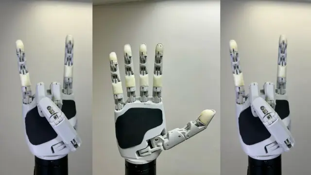
$314Aero Hand Open is an open-source, tendon-driven robotic hand designed by TetherIA for dexterous manipulation research. Unlike expensive proprietary solutions, this hand focuses on simplicity, reliability, and accessibility — fully 3D-printed structure with off-the-shelf electronic components. Key Specs: 7 DoF | 16 joints | 5 fingers | 389g | ESP32-S3 controller | 7× Feetech HLS3606M servos Attribution: TetherIA Inc. — https://github.com/TetherIA/aero-hand-open License: Design files (CAD/STL/BOM/docs) — CC BY-NC-SA 4.0 | Software (firmware/SDK) — Apache-2.0 Source: https://github.com/TetherIA/aero-hand-open Docs: https://docs.tetheria.ai | Shop: https://shop.tetheria.ai Printing This is a single left hand (all parts are prefixed; the upstream repo also publishes a mirrored right hand under prefixes if you need the opposite hand). Structural / palm (1 each): leftbaselink — palm/chassis lefttlink — thumb carpometacarpal mount Five finger chains. Each of the four fingers (index, middle, ring, pinky) is a four-link chain; the thumb is its own four-link chain: Index: leftindexproximal / middle / distal / tip Middle: leftmiddleproximal / middle / distal / tip Ring: leftringproximal / middle / distal / tip Pinky: leftpinkyproximal / middle / distal / tip Thumb: leftthumbmcp / proximal / distal / tip Mount adapters (pick the one that matches your wrist/base — optional): 135degreesadapter — for a 135° angled mount threadedmountadapter — for a threaded base mount Print in PLA, 0.2 mm layer height, tree supports on the build plate only. Per the BOM, several small hardware items are not separate STLs: the 6× cable spools and the silicone finger pads are produced by other means (spools are integral / cast pads use Ecoflex 00-30 in a mold). Buy undersized 2x10 pins — standard 2x10 pins are too tight for the 2x5x2.5 mm bearings and cause joint stiffness. Route the tendons before final assembly of each finger module; retrofitting cables through assembled joints is extremely difficult. The full set is 24 STL files (22 hand parts + 2 optional mount adapters), driven by 7× Feetech HLS3606M servos.
 Other Robots
Flix Quadcopter
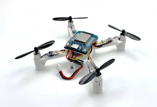
$40Flix (flight + X) is an open-source ESP32-based quadcopter built from scratch, designed for education and research. It features a 3D-printed frame, 4× brushed motors, MAVLink communication over Wi-Fi or ESP-NOW, and clean Arduino firmware under 2,000 lines. Control it with a USB gamepad, RC transmitter, or smartphone — and automate flights with the included Python library. A Gazebo simulator runs the original firmware code for safe development. Attribution Author: Oleg Kalachev (@okalachev) License: MIT Source: https://github.com/okalachev/flix Version: 1.1 (3D-printed frame)
 Camera Bots
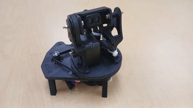
vdar — 3D LiDAR Scanner
$100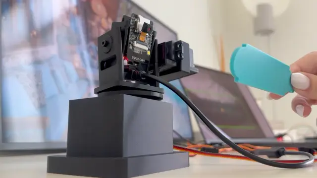 Camera Bots
ESP32-CAM AI Object Tracking Camera
$50ESP32-CAM AI Object Tracking Camera A DIY pan/tilt camera that finds a custom target object with a trained YOLO model and physically turns to follow it. An ESP32-CAM streams live video over Wi-Fi to a laptop; Python runs the YOLO detector and sends movement deltas over serial to a second ESP32-WROOM-32 board, which drives two servos through a PCA9685 driver. All mechanical parts are 3D printed from an OpenSCAD source, so the mount can be resized for different servos and camera boards. This is orobot's first entry combining on-device Wi-Fi video streaming with a trained computer-vision model driving physical actuators — most of the catalog's vision work is closed-loop on a single board; this one splits video capture (ESP32-CAM), inference (laptop/YOLO), and actuation (second ESP32 + PCA9685) across three hops. How It Works What You'll Need ESP32-CAM module (the video source) ESP32-WROOM-32 DevKit board (the servo controller) PCA9685 16-channel PWM/servo driver 2x MG995/MG996-style servos (pan + tilt) External 5V power supply for the servos Jumper wires, M3 screws, micro screws for the ESP32-CAM module 3D-printed mount parts (STLs included; OpenSCAD source included for resizing) A laptop to run the Python + YOLO tracking script Build Notes The servos are powered externally at 5V — the ESP32 shouldn't power them directly, they draw more current than its regulator is rated for. I2C wiring: ESP32 GPIO21 -> PCA9685 SDA, GPIO22 -> PCA9685 SCL. All grounds must be tied together (ESP32, PCA9685, and the external 5V supply). The trained YOLO model () was trained on a custom 3D-printed target object — swap in your own dataset via and to track something else. For real-time tracking, a smaller/faster video stream tracked better than a high-resolution one with too much latency — the source project runs the ESP32-CAM at a reduced frame size for this reason. This is an actively-evolving prototype per the source author — movement smoothing, wiring, and the printed parts are still being refined upstream. orobot Learning Interface The orobot program here exposes the pan and tilt axes as motor slots you can jog directly from the browser (joystick, center button, scan sweep) to learn the control surface. The full AI tracking loop (YOLO inference + serial bridge) still runs on your own machine per the source repo's Python setup — this program is a hardware-control on-ramp, not a port of the vision pipeline. Attribution Creator: mmm1712 Source: github.com/mmm1712/ESP32-CAM-AI-Object-Tracking Commit: e7a6c06c9986dae844f30cb7bdddff821d888e5d License: Shared by the author for learning and experimentation (no formal OSS license file in the source repo — confirm terms with the author before commercial use)
 Mobile Robots
Maker's Pet Loki
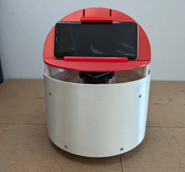
$66Maker's Pet Loki is an open-source, 3D-printed home pet robot built on the Kaia.ai ROS2 robotics platform. It's a 200mm round differential-drive base sized to fit common 210x250mm and 220x220mm print beds, topped with a spinning laser distance sensor for room mapping and a phone/tablet mount that doubles as its "face." Loki uses two BLDC gearmotors for locomotion, a spinning LiDAR (YDLIDAR X4/X3/X2, Neato XV11, LDS02RR, or RPLIDAR A1 are all supported) for 360-degree room scanning, and an ESP32 microcontroller running Kaia.ai's Arduino/micro-ROS firmware to bridge sensors and motors to a ROS2 stack. Once paired with the Kaia.ai software (ROS2 Humble/Iron via Docker), Loki can autonomously map a room (Cartographer SLAM), navigate with Nav2, explore unknown spaces, and be driven manually via keyboard teleop. What you get in this Program: The 3D-printable STL parts for the round chassis, head, bumpers, battery pack, and sensor mounting plates (choose the plate matching your LiDAR model) A learning-mode control stub (drive + stop) that runs in the orobot IDE, so you can explore the Program Editor pattern before wiring up the real Kaia.ai ROS2 stack The real build: 3D print the parts, assemble per the official videos, flash the kaiaai/firmware Arduino sketch to an ESP32, then bring up ROS2 via the Kaia.ai Docker setup Attribution: Design, firmware, and ROS2 packages by Ilia O. / Maker's Pet (REMAKE.AI), licensed Apache 2.0. Source: https://github.com/makerspet/makerspetloki (STL/CAD files live in the companion repo https://github.com/makerspet/3dmodels, firmware in https://github.com/kaiaai/firmware). Hardware note: Loki's real self-driving stack (ROS2, Cartographer SLAM, Nav2) runs on the ESP32 + micro-ROS + a companion PC/laptop over WiFi, not on orobot's own firmware. This Program's device code is a simplified learning stub for the orobot IDE — full autonomous behavior requires following the upstream build/bring-up instructions.
 Camera Bots
Turret Face Tracker
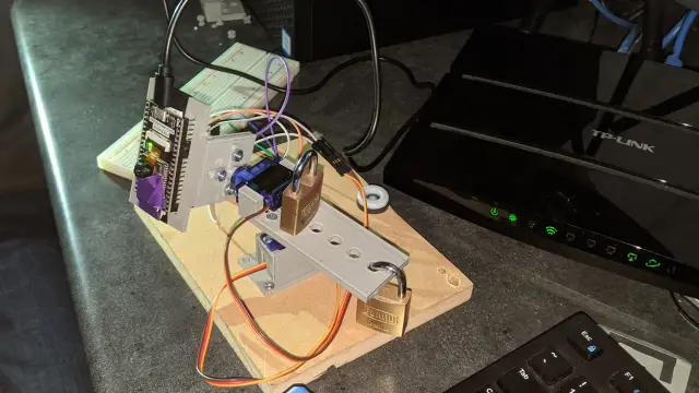
$35Turret Face Tracker — An ESP32 Head That Watches You Back A two-servo pan/tilt turret with an onboard ESP32-Wrover camera that detects a face in its own video frame and turns to keep it centered — no laptop, no external vision server, no cloud inference. Camera capture, face detection, and the proportional pan/tilt control loop all run on the microcontroller itself. Point it at a desk, connect to its local WiFi web UI, click "Start Stream," and it starts hunting for your face. Built for a high-school computer-technology class (TEJ) by Rylan Hachey, Ashish Agrahari, and Noah Raymond, using the stock ESP32 camera example's face-detection pipeline as the vision core. How It Works An ESP32-Wrover module (PSRAM required — needed for the frame buffer that face detection runs against) hosts its own WiFi access point and a browser-based camera viewer. Enabling "Face Detection" in that viewer draws a box around any face in frame and exposes its , , , through the sketch. The main loop maps the face box's offset from center into pan/tilt servo angles ( from pixel offset to ±90°), moving two SG90-class micro servos on 3D-printed brackets. If no face is seen for ~500 loop iterations, it drops into a search mode: sweeping pan back and forth and stepping tilt, until a face reappears. Build Overview Compute + camera: ESP32-Wrover dev board (Freenove or similar, PSRAM required for face detection) Actuators: 2x SG90-class micro servos — pan (pin 12) and tilt (pin 13) Structure: 3D-printed camera mount, pan bracket, and tilt bracket (originally modeled in Autodesk Inventor; STLs included) Firmware: Arduino IDE sketch (), built on Espressif's + libraries Wiring PAN servo signal → ESP32 pin 12 TILT servo signal → ESP32 pin 13 Both servos' power → ESP32 VCC Both servos' ground → ESP32 GND Flashing the Firmware 1. Install ESP32 board support in the Arduino IDE (setup guide). 2. Board: ESP32 Wrover Module. Partition Scheme: Huge APP (3MB No OTA/1MB SPIFFS). 3. Set your WiFi SSID/password in the sketch, upload to the board. 4. Find the board's IP (Serial Monitor, or your router's client list) and open it in a browser. 5. Click Start Stream, set XCLK = 10MHz, enable V-Flip, Resolution = QVGA (320x240), WB Mode = Sunny, then enable Face Detection. 6. Sit in frame — the turret should start tracking your face. Note on orobot Control This build's face-tracking loop is entirely self-hosted on the ESP32 — it does not speak the orobot device protocol, so full closed-loop autonomous tracking happens on the board itself, reachable through its own local web UI rather than through orobot.io. The control interface on this page is a learning stub: a simplified pan/tilt joystick/pose demo using the same 2-servo shape, so you can explore the orobot Program IDE API alongside the original firmware. Flash the linked Arduino sketch to your ESP32-Wrover for the actual closed-loop face-tracking behavior shown in the photos. Attribution & License Creators: Rylan Hachey, Ashish Agrahari, Noah Raymond (FHCI, TEJ Computer Technology class) Source repository: github.com/AshishA26/Turret-Face-Tracker License: No license file is published in the source repository (defaults to all-rights-reserved under GitHub's terms) — this Program links to and credits the original source rather than redistributing it under an open license. 3D-printed parts (STL) are mirrored here for convenience with full attribution; consult the original authors before commercial reuse.
 mobile-robots
MARPY
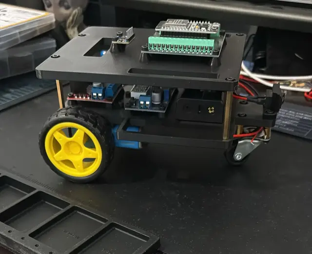
$40Most Affordable ROS2 Platform Yet
Browse by type
Browse by hardware
Browse by difficulty